T113-S3 SPI clk 波形异常
-
此回复已被删除! -
我对 Keysight 示波器不太熟悉,但我理解的没错吧,信号是用 1 倍探头而不是 10 倍探头探测的?
这一点很重要,因为使用 1 倍探头会大幅降低带宽。
你的 SPI 时钟频率设置为 100MHz,需要一台性能良好的示波器才能正确显示信号。构成方波的谐波是奇次谐波,因此示波器的带宽需要远大于 100MHz,并且采样率也要与之匹配。
所以在我看来,你示波器上的波形看起来并不算异常,尤其考虑到 3.3V 的信号经过截止频率约为 6MHz 的一阶探头滤波器衰减后,其幅度会远小于 3.3V 的输出电压。
Translated from English:
I'm not familiar with keysight scopes, but am I right when saying that the signal is probed with a 1x probe instead of 10x.
Why this is important, is that with a 1x probe the bandwidth is reduced quite a bit.
With your SPI clock set to 100MHz one needs a good scope to see a proper representation of the signal. The harmonics that make up the square wave are the odd ones, so the scope needs to have a bandwidth of way more than 100MHz and a sampling rate to go with it.
So to me the trace on your scope does not look that abnormal, also considering that a 3.3V signal reduced by a first order probe filter with a cutoff point around 6MHz will be far less than the 3.3V output. -
你发的文字参数里spi的频率配置是100MHz,但是从图片的代码上看是10MHz。再从示波器的波形上看,100ns一格,算下来应该是10MHz的波形。所以现在跑的SPI频率应该是10MHz。10Mhz频率理论上就算是100Mhz带宽的示波器应该也能抓到才对。按照采样定理只要2倍以及以上的采样率采集应该都能采到。可以尝试将示波器的探头配置为10X,示波器也同步配置成10X。使用1X探头会降低带宽。时钟应该是正常的,比较怀疑是示波器的配置问题。也可以尝试探头点信号,直接Auto set,让示波器自识别一波。
-
spi 用的是10Mhz的时钟,这里测到的也是10MHz
-
@jaron
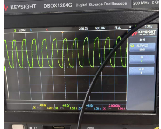
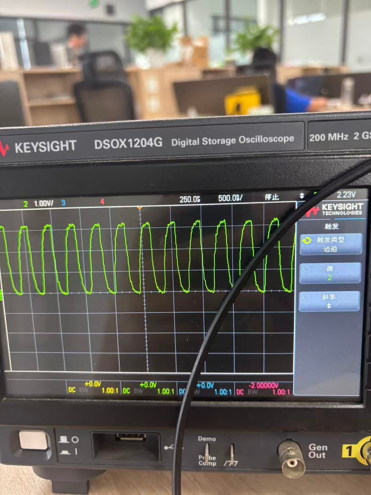
这是2Mhz的信号 -
另外测试了频率低的时钟,波形是有很大改善的。
请教下spi的时钟如何降频,测试了500Khz,1Mhz,8Mhz都不行,spi发送超时,2Mhz的情况下,偶尔出现发送超时。该如何设置频率低的时钟呢? -
@pcat113s4user 感谢您的回答,我测试10倍探头,确实波形就比较正常了
-
-
@pcat113s4user خیلی عالی

Copyright © 2024 深圳全志在线有限公司 粤ICP备2021084185号 粤公网安备44030502007680号