【XR806开发板试用】新建任务及点灯那些事
-
现在我们已经成功地完成了helloworld了,接下来就是一些个性化的开发了
首当其冲就是最基础的IO开发
下面演示如何添加自己的任务文件到系统中
1、在
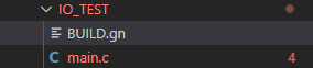
Harmony\device\xradio\xr806\ohosdemo下新建文件夹,比如起名IO_TEST。
并新建main.c文件和BUILD.gn文件(建议严格按这个形式命名),后续文
件数变多的情况下也可以在任务路径下分别新建头文件和c文件的文件夹,并重新指定路径即可。
2、接下来是BUILD.gn文件(关于GN跨平台工具,想具体学习可以参考此文章https://www.cnblogs.com/bigben0123/p/12643839.html)gn文件内容如下
#Create by Randolph.

import("//device/xradio/xr806/liteos_m/config.gni")

static_library("app_IO")
{
   configs = []

   sources = ["main.c",]

   cflags = board_cflags

   include_dirs = board_include_dirs
   include_dirs += [
      "//kernel/liteos_m/kernel/arch/include",
   ]
}
此处要注意的是。对static_library静态库的声明需要按照app_xxx的格式写入
3、完成了之后,c文件能自主发挥的空间就很大了。先放上代码
//Create by Randolph #include <stdio.h> #include "kernel/os/os.h" #include "ohos_init.h" #include "driver/chip/hal_gpio.h" #define GPIO_OUTPUT_PORT GPIO_PORT_A static OS_Thread_t g_main_thread; static void gpio_output_init(void) { GPIO_InitParam param; param.driving = GPIO_DRIVING_LEVEL_1; param.mode = GPIOx_Pn_F1_OUTPUT; param.pull = GPIO_PULL_NONE; HAL_GPIO_Init(GPIO_OUTPUT_PORT, GPIO_PIN_21, ¶m);//led灯对应IO } static void gpio_output_ctl(uint8_t level) { HAL_GPIO_WritePin(GPIO_OUTPUT_PORT, GPIO_PIN_21, level ? GPIO_PIN_HIGH : GPIO_PIN_LOW); } // static void gpio_output_deinit(void) // { // HAL_GPIO_DeInit(GPIO_OUTPUT_PORT, GPIO_PIN_15); // } // gpio_output_deinit();//GPIO去初始化,如果IO要去做别的事情就可以执行,我这边只点灯 static void gpio_output_test(void) { printf("gpio output test start.\n"); uint8_t i; uint8_t level = 1; for (i = 0; i < 10; i++) { gpio_output_ctl(level); printf("gpio level write %d\n", level); level = (!level & 0x01); OS_MSleep(500); } printf("gpio output test end.\n"); } static void MainThread(void *arg) { printf("Hello,XR806 This is Randolph!\n"); while (1) { gpio_output_test(); } } void IO_TestMain(void) { printf("Test Start\n"); gpio_output_init(); if (OS_ThreadCreate(&g_main_thread,"MainThread",MainThread, NULL, OS_THREAD_PRIO_APP, 4096) != OS_OK) { printf("[ERR] Create HelloWorld_Task Failed\n"); } } SYS_RUN(IO_TestMain);此处就跟玩stm32一类的主控一样了,大部分都是调用hal库,另外在
Harmony\device\xradio\xr806\xr_skylark\project\example路径内也有很多现成的例子可以参考。
当然也可以用鸿蒙的外设接口,不用原生SDK的。文件接口的头文件在:base\iot_hardware\peripheral\interfaces\kits源码在:
device\xradio\xr806\adapter\hals\iot_hardware\wifiiot_lite带有iot字样的接口就是鸿蒙的接口。
4、最后在
Harmony\device\xradio\xr806\ohosdemo\BUILD.gn路径下增加我们新建的任务文件信息如下:
"IO_TEST:app_IO"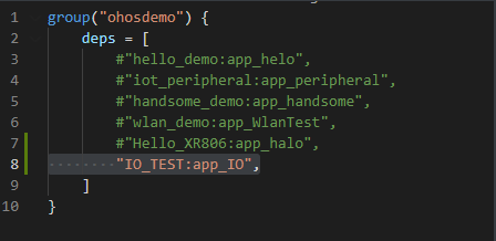
别忘记注释掉之前的hello world!保存后,回到Harmony跟目录执行hb build -f
并在phoenixMC.exe中烧录镜像,就可以看到板子上的灯闪烁起来啦!
同时也可以从串口看到调试信息:

点灯完成! -
由于手上没什么外设,决定继续从led下手。用鸿蒙的接口来实现个呼吸灯。根据OpenHarmony的要求,适配了OpenHarmony后就只有一个接口,没有原生接口了,所以之后的文档中我就不区别对待了,统一指OpenHarmony接口。
关于呼吸灯的原理,就是PWM(Pulse Width Modulation),即脉宽调制信号,应用非常广泛。最主要的特点为可以通过改变数字信号的占空比,从而达到模拟信号的效果。因此理论上只要带宽足够,任何模拟值都可以使用PWM信号进行编码。
接下来我们开始对XR806进行PWM实验:1、在Harmony\device\xradio\xr806\ohosdemo下新建任务文件夹如Breath_LED,分别添加BUILD.gn文件和main.c文件
其中BUILD.gn文件内容如下:
import("//device/xradio/xr806/liteos_m/config.gni")

static_library("app_BreathLED")
{
   configs = []

   sources = ["main.c",]

   cflags = board_cflags

   include_dirs = board_include_dirs
   include_dirs += [
      "//kernel/liteos_m/kernel/arch/include",
      "//base/iot_hardware/peripheral/interfaces/kits",
      "//device/xradio/xr806/xr_skylark/src/rom/rom_bin/src/driver",
   ]
}
其中静态库必须以app_xxx的格式命名。
2、从代码编辑器中打开文件夹,找到device\xradio\xr806\adapter\hals\iot_hardware\wifiiot_lite 文件夹下内容,此为专门的外设接口,能看到flash、gpio、i2c、pwm等参考源文件,文件接口的头文件在base\iot_hardware\peripheral\interfaces\kits。这里我们打开iot_pwm.c文件,可以看到如下函数:
1、IoTPwmInit(unsigned int port)
2、IoTPwmDeinit(unsigned int port)
3、IoTPwmStart(unsigned int port, unsigned short duty,
			 unsigned int freq)
4、IoTPwmStop(unsigned int port)
其中 IoTPwmInit 和 IoTPwmDeinit 就是port的初始化跟去初始化,填入端口参数即可使用。IoTPwmStart 和 IoTPwmStop 就是pwm的开启与关闭。
3、接下来我们就可以开始写main.c文件的内容了。
#include <stdio.h>
#include "kernel/os/os.h"
#include "ohos_init.h"
#include "iot_pwm.h"

#define PWM_OUTPUT_CHL        	PWM_GROUP1_CH2

static OS_Thread_t g_main_thread;

static void Breath_LED_init()
{
    IoTPwmInit(GPIO_PORT_A);//初始化pwm端口,设置时钟信号源和分频系数等
}

 static void Breath_LED_start(void)
 {
    unsigned char counter = 1;

	for(counter = 1; counter<99; counter++)
	{
		IoTPwmStart(PWM_OUTPUT_CHL,counter,100);//升频
		OS_MSleep(10);
	}
	for(counter = 99; counter >1; counter--)
	{
		IoTPwmStart(PWM_OUTPUT_CHL,counter,100);//降频
		OS_MSleep(10);
	}

 }

static void MainThread(void *arg)
{
    Breath_LED_init();
	while (1)
    {
        Breath_LED_start();
	}
}

void PWM_TestMain(void)//实际入口,负责创建线程
{
	printf("Test Start\n");

	if (OS_ThreadCreate(&g_main_thread,"MainThread",MainThread, NULL, OS_THREAD_PRIO_APP, 4096) != OS_OK)
	{
		printf("[ERR] Create PWMLED_Task Failed\n");
	}
}

SYS_RUN(PWM_TestMain);
//Harmony线程入口,在utils/native/lite/include/ohos_init.h中定义,读者可以改成其他入口类型检查差异
4、配置复用端口
关于端口信息可以在PWM_CH_ID这个枚举体中查看到:
typedef enum { PWM_GROUP0_CH0 = 0U, /*!< bit 0 PORTA_PIN8 or PORTA_PIN19 */ PWM_GROUP0_CH1 = 1U, /*!< bit 1 PORTA_PIN9 or PORTA_PIN20 */ PWM_GROUP1_CH2 = 2U, /*!< bit 2 PORTA_PIN10 or PORTA_PIN21 */ PWM_GROUP1_CH3 = 3U, /*!< bit 3 PORTA_PIN11 or PORTA_PIN22 */ PWM_GROUP2_CH4 = 4U, /*!< bit 4 PORTA_PIN12 or PORTB_PIN0 */ PWM_GROUP2_CH5 = 5U, /*!< bit 5 PORTA_PIN13 or PORTB_PIN1 */ PWM_GROUP3_CH6 = 6U, /*!< bit 6 PORTA_PIN14 or PORTB_PIN2 */ PWM_GROUP3_CH7 = 7U, /*!< bit 7 PORTA_PIN15 or PORTB_PIN3 */ PWM_CH_NUM = 8U, PWM_CH_NULL = PWM_CH_NUM, } PWM_CH_ID;由于笔者的开发板上的led连接的是pin21,故在选择PWM通道时应该选择通道二,也就是PWM_GROUP_CH2, 但是值得注意的一点是有的开发板配置时考虑到IO复用问题,并没有开启相应的端口,因此需要手动配置一下。
打开
Harmony\device\xradio\xr806\xr_skylark\project\common\board\xr806_OHOS\board_config.c可以看到关于pwm的相关端口配置
__xip_rodata
static const GPIO_PinMuxParam g_pinmux_pwm[] = {
	{ GPIO_PORT_A, GPIO_PIN_19,  { GPIOA_P19_F4_PWM0_ECT0, GPIO_DRIVING_LEVEL_1, GPIO_PULL_NONE } },
	{ GPIO_PORT_A, GPIO_PIN_20,  { GPIOA_P20_F4_PWM1_ECT1, GPIO_DRIVING_LEVEL_1, GPIO_PULL_NONE } },
	{ GPIO_PORT_A, GPIO_PIN_22,  { GPIOA_P22_F4_PWM3_ECT3, GPIO_DRIVING_LEVEL_1, GPIO_PULL_NONE } },
	{ GPIO_PORT_A, GPIO_PIN_12,  { GPIOA_P12_F3_PWM4_ECT4, GPIO_DRIVING_LEVEL_1, GPIO_PULL_NONE } },
	{ GPIO_PORT_A, GPIO_PIN_13,  { GPIOA_P13_F3_PWM5_ECT5, GPIO_DRIVING_LEVEL_1, GPIO_PULL_NONE } },
	{ GPIO_PORT_B, GPIO_PIN_3,   { GPIOB_P3_F4_PWM7_ECT7,  GPIO_DRIVING_LEVEL_1, GPIO_PULL_NONE } },
};
可以看到其中是没有pin21的信息的,所以需要手动添加一句
{ GPIO_PORT_A, GPIO_PIN_21, { GPIOA_P21_F4_PWM2_ECT2, GPIO_DRIVING_LEVEL_1, GPIO_PULL_NONE } },这样就可以正常开启pwm了。
如果在其他开发中遇到调用sdk后编译正常开发板却没有响应的情况,也可以产看关于引脚复用的文档寻找问题。
5、编译烧录
最后不要忘记在/Harmony\device\xradio\xr806\ohosdemo\BUILD.gn中加入我们的任务
group("ohosdemo") {
    deps = [
        #"iot_peripheral:app_peripheral",
        #"handsome_demo:app_handsome",
        #"wlan_demo:app_WlanTest",
        "Breath_LED:app_BreathLED"
    ]
}
根目录命令行执行hb build -f,然后就可以跟hello world中一样过程烧录了。
烧录后就可以看到板载呼吸灯的效果了。
-
XR806_PIN_MUX.pdf 此为引脚复用文档。
-
测试下论坛的mp4[normal video.mp4](/assets/uploads/files/1639982301992-normal-video.mp4) https://bbs.aw-ol.com/assets/uploads/files/1639982301992-normal-video.mp4 测试下论坛的mp4
Copyright © 2024 深圳全志在线有限公司 粤ICP备2021084185号 粤公网安备44030502007680号