(一)初始化蓝牙
# 复位蓝牙
echo 0 > /sys/class/rfkill/rfkill0/state
sleep 1
echo 1 > /sys/class/rfkill/rfkill0/state
sleep 1

# 绑定蓝牙设备
hciattach -n ttyS1 xradio > /dev/null 2>&1 &
sleep 8

# 启用蓝牙设备
hciconfig hci0 up
hciconfig hci0 piscan
(二)Linux下蓝牙工具(bluez 工具集)
- hcitool、bluetoothctl等工具,可以进行BLE设备的扫描、连接、配对、广播等操作
- hcitool 可以发送HCI command,设置BLE的广播数据
- bluetoothctl 可以新增蓝牙服务,返回回调等操作
- sdptool 查看蓝牙信息和提供的服务
- hciconfig 查看蓝牙信息
- l2ping 测试蓝牙的连通性
- gatttool :可以在GATT层面,完成GATT profile的连接、service
- attribute的读写等操作
(三)蓝牙扫描
hcitool scan 	#扫描经典蓝牙

hcitool lescan	 #扫描BL低功耗蓝牙
(四)使用Bluetoothctl创建蓝牙服务
1、先启动蓝牙,进入可搜索状态
# 复位蓝牙
echo 0 > /sys/class/rfkill/rfkill0/state
sleep 1
echo 1 > /sys/class/rfkill/rfkill0/state
sleep 1

# 绑定设备
hciattach -n ttyS1 xradio > /dev/null 2>&1 &
sleep 8

# 启用蓝牙设备
hciconfig hci0 up
hciconfig hci0 piscan

# 免认证
hciconfig hci0 auth
# 广播
hciconfig hci0 leadv
2、进入 bluetoothctl 交互界面
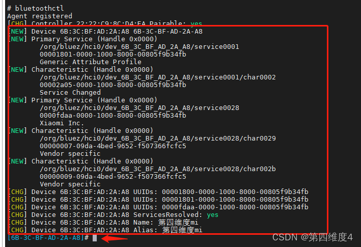
# bluetoothctl
Agent registered
[CHG] Controller 22:92:C9:8C:04:EA Pairable: yes
[bluetooth]#
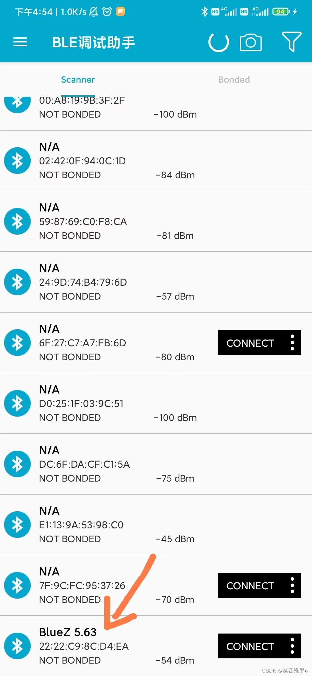
3、手机使用BLE调试助手连接蓝牙,如下图所示
4、连接后,bluetoothctl会发生变化,此时已经进入交互界面
4、但是我们没有其他服务,只能做一些简单的操作,比如读取,因为现有的服务是 bluetoothctl 提供的
5、下面我们添加自己的服务
5.1 进入菜单
[6B-3C-BF-AD-2A-A8]# menu gatt
Menu gatt:
Available commands:
-------------------
list-attributes [dev/local]                       List attributes
select-attribute <attribute/UUID>                 Select attribute
attribute-info [attribute/UUID]                   Select attribute
read [offset]                                     Read attribute value
write <data=xx xx ...> [offset] [type]            Write attribute value
acquire-write                                     Acquire Write file descriptor
release-write                                     Release Write file descriptor
....
5.2 添加自己的service和characteristic
[bluetoothctl] register-service 0xFFFF # (Choose yes when asked if primary service)
[bluetoothctl] register-characteristic 0xAAAA read       # (Select a value of 1 when prompted)# 输入的值是初始值,每次读取,会加一
[bluetoothctl] register-characteristic 0xBBBB read,write # (Select a value of 0 when prompted)
[bluetoothctl] register-characteristic 0xCCCC read       # (Select a value of 2 when prompted)
[bluetoothctl] register-application # (This commits the services/characteristics and registers the profile)
[bluetoothctl] back
[bluetoothctl] advertise on
通过 show 操作可以看到刚才添加的0xffff 服务
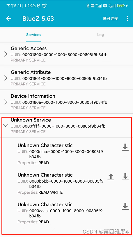
5.3 手机重新连接蓝牙
服务从 3 项变为 4 项,第 4 项即为我们刚才添加的服务。
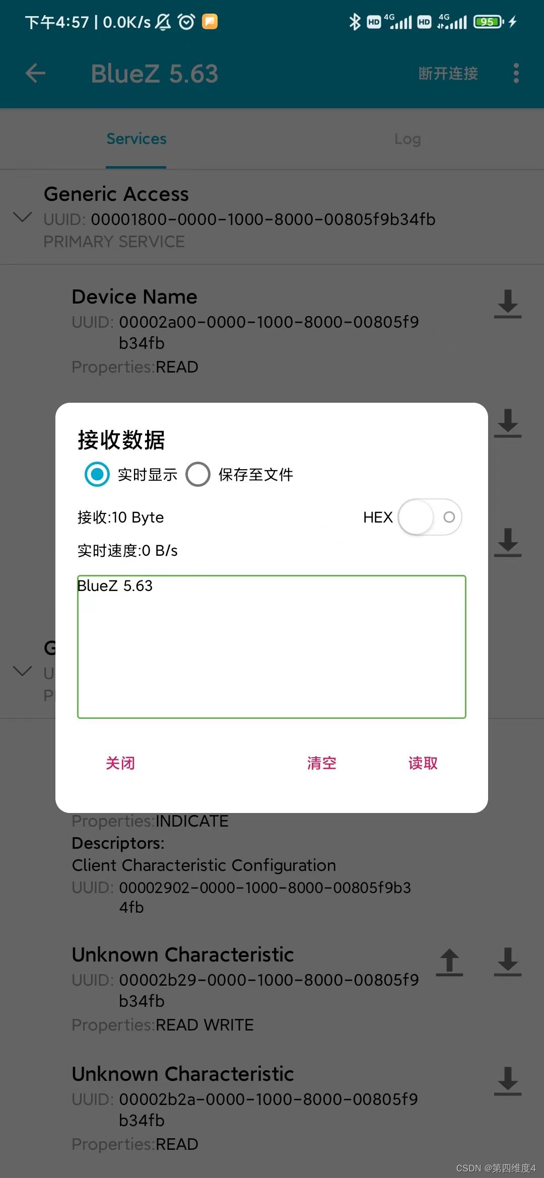
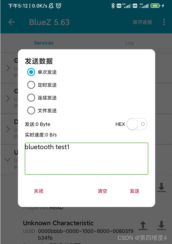
5.4 读写操作
在有上传按钮的服务上传数据
此时收到:
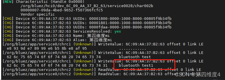
读操作的话,直接读取就好了,值为刚才我们设置的值。
至此测试完毕
(五)其他操作
1、启动/关闭/重启蓝牙
hciconfig hci0 up  		#启动蓝牙设备
hciconfig hci0 off 		#关闭蓝牙设备
hciconfig hci0 reset 	#重启蓝牙设备
2、测试蓝牙是否可达 l2ping
l2ping -i hci0 -c 4 21:12:A3:C4:50:66
3、查看功能与服务
sdptool browse local # local可以改成其它蓝牙的mac地址
4、查看蓝牙的状态和信息
hciconfig -a
5、查看蓝牙设备
hcitool dev
Devices:
        hci0    22:22:2A:B0:9C:3C
6、开启/关闭蓝牙广播
hciconfig hci0 leadv / noleadv
7、查看已经连接的BLE设备
(此时调试助手已经连接)
hcitool -i hci0 con
Connections:
        > LE 60:AB:D1:B5:A6:FB handle 0 state 1 lm PERIPHERAL
8、 蓝牙认证打开/关闭
直接体现在进行蓝牙连接时,是否输入连接PIN密码,用于PIN配对
hciconfig hci0 auth/noauth
9、 查看/改变蓝牙主从状态
hciconfig hci0 lm master、hciconfig hci0 lm slave
10、查看/设置蓝牙名称
hciconfig hci0 name 、hciconfig hci0 name BLXX
11、 查看支持的链路层状态
hciconfig hci0 lestates
12、列出低功耗蓝牙的服务
bluetoothctl --monitor gatt.list-attributes
其他操作自己慢慢摸索哈,我一个人只能啃成这样了,如有写得不对的地方大佬指正。
原文链接:https://blog.csdn.net/qq_46079439/article/details/126244998