导航

    全志在线开发者论坛

    • 注册
    • 登录
    • 搜索
    • 版块
    • 话题
    • 在线文档
    • 社区主页
    1. 主页
    2. zznzzn
    3. 帖子
    • 资料
    • 关注 2
    • 粉丝 2
    • 我的积分 3539
    • 主题 44
    • 帖子 61
    • 最佳 4
    • 群组 0

    zznzzn 发布的帖子

    • 基于全志T507-H的Linux-RT + Igh EtherCAT主站案例分享

      本文将为各位工程师演示全志T507-H工业评估板(TLT507-EVM)基于IgH EtherCAT控制伺服电机方法,生动说明Linux-RT + Igh EtherCAT的强大之处!

      Linux-RT系统的优势

      • 内核开源、免费、功能完善。

      • RT PREEMPT补丁,使Linux内核成为硬实时操作系统,无需完整的内核重写。

      • 既有实时性,又有相同的开发生态系统(包括相同工具链、文件系统和安装方法,以及相同的POSIX API等),实现产品快速上市的期望。

      Linux-RT实时性测试(Cyclictest工具)

      Cyclictest常用于实时系统的基准测试,是评估实时系统相对性能的最常用工具之一。Cyclictest反复测量并精确统计线程的实际唤醒时间,以提供有关系统的延迟信息。它可测量由硬件、固件和操作系统引起的实时系统的延迟。

      基于全志T507-H(硬件平台:创龙科技TLT507-EVM评估板),按照创龙科技提供的案例用户手册进行操作,使用Cyclictest程序测试系统实时性,得出如下测试结果。

      在这里插入图片描述

      在这里插入图片描述

      对比测试数据,可看到基于Linux-RT-4.9.170内核的系统的延时更加稳定,最大延时更低,系统实时性更佳。

      Linux-RT性能测试

      基于全志T507-H(硬件平台:创龙科技TLT507-EVM评估板),按照创龙科技提供的案例用户手册进行操作,测试分别在CPU空载、满负荷(运行stress压力测试工具)、隔离CPU核心的情况下,得出如下测试结果。

      备注:测试数据与实际测试环境有关,仅供参考。

      在这里插入图片描述

      CPU空载状态测试,CPU0、CPU1核心Max Latencies值最大,为69us,CPU3核心的Max Latencies值最小,为66us。

      在这里插入图片描述

      CPU满负荷状态测试,CPU0核心Max Latencies值最大,为88us,CPU3核心的Max Latencies值最小,为64us。

      在这里插入图片描述

      隔离CPU核心状态测试,CPU0核心Max Latencies值最大,为73us,隔离CPU3核心的Max Latencies值最小,为41us。

      根据CPU空载、CPU满负荷、隔离CPU核心三种状态的测试结果可知:当程序指定至隔离的CPU3核心上运行时,Linux系统延迟最低,可有效提高系统实时性。故推荐对实时性要求较高的程序(功能)指定至T507-H隔离的CPU核心运行。

      基于全志T507-H的Linux-RT + IgH EtherCAT主站演示

      下文主要介绍基于全志T507-H(硬件平台:创龙科技TLT507-EVM评估板)案例,按照创龙科技提供的案例用户手册进行操作得出测试结果。

      本次演示的开发环境:

      • Windows开发环境:Windows 7 64bit、Windows 10 64bit
      • Linux开发环境:Ubuntu18.04.4 64bit
      • 虚拟机:VMware16.2.5
      • U-Boot:U-Boot 2018
      • Kernel:Linux-RT-4.9.170
      • LinuxSDK:LinuxSDK-[版本号].tar.gz(基于全志官方V2.0_20220618)
      • IgH EtherCAT:ethercat-stable-1.5-gcd0d17d-20210723
      • 伺服驱动器:台达ASD-A2-0121-E
      • 伺服电机:台达ECMA-C10401GS
      • 硬件平台:TLT507-EVM评估板(基于全志T507-H)

      IgH EtherCAT简介

      IgH EtherCAT为运行于Linux系统的免费开源EtherCAT主站程序,框架如下所示,

      在这里插入图片描述

      IgH EtherCAT主站通过构建Linux字符设备,应用程序通过对字符设备的访问实现与EtherCAT主站模块的通信。

      IgH EtherCAT开发包提供EtherCAT工具,该工具提供各种可在Linux用户层运行的命令,可直接实现对从站的访问和设置,如设置从站地址、显示总线配置、显示PDO数据、读写SDO参数等。

      案例说明

      案例功能:EtherCAT通讯周期时间为1ms,控制伺服电机正转和反转,并通过串口循环打印EtherCAT通讯周期时间的最大值和最小值。

      (1)正转:伺服电机目标速度从0加速到10000,当达到10000速度后,控制伺服电机减速至0,循环运行。

      (2)反转:伺服电机目标速度从0加速到-10000,当达到-10000速度后,控制伺服电机减速至0,循环运行。

      在这里插入图片描述

      为便于测试,我司提供已验证的基于Linux-RT编译生成的内核镜像文件和内核模块,位于产品资料“4-软件资料\Linux\Kernel\image\linux-4.9.170-[版本号]-[Git系列号]\”目录下。

      请将Linux-RT内核镜像boot-rt.fex和Linux-RT内核配套的内核模块modules-rt目录下4.9.170-[版本号]-[Git系列号].tar.gz压缩包的拷贝至评估板文件系统目录下。

      执行如下命令,将boot-rt.fex重命名为boot.fex,同时将内核模块压缩包解压。

      Target#mv boot-rt.fex boot.fex
      
      Target#tar -zxf 4.9.170-rt129-g4c65c66.tar.gz
      

      在这里插入图片描述

      执行如下命令替换内核镜像和内核模块,评估板重启生效。

      备注:mmcblk1为Micro SD对应的设备节点,如需固化至eMMC,请将设备节点修改为mmcblk0。

      Target#dd if=boot.fex of=/dev/mmcblk1p3 conv=fsync
      
      Target#rm /lib/modules/* -rf
      
      Target#cp $(uname -r) /lib/modules/ -r
      
      Target#sync
      
      Target#reboot
      

      在这里插入图片描述

      在这里插入图片描述

      案例测试

      请按下图所示使用网线连接评估板ETH0 RGMII网口和伺服驱动器A的IN网口,将伺服驱动器A的OUT网口使用网线连接至伺服驱动器B的IN网口。

      在这里插入图片描述
      在这里插入图片描述
      为便于测试,我司提供的经验证的IgH EtherCAT主站程序为案例"igh_ethercat\images"目录下的ethercat-stable-1.5-gcd0d17d.tar.gz压缩包,将其拷贝至评估板文件系统任意目录下。

      执行如下命令,解压ethercat-stable-1.5-gcd0d17d.tar.gz压缩包将会得到_install文件夹。

      Target#tar -zxf ethercat-stable-1.5-gcd0d17d.tar.gz
      

      在这里插入图片描述

      执行如下命令,并查询评估板网卡物理地址。

      Target#ifconfig
      

      在这里插入图片描述

      执行如下命令,加载驱动模块。

      Target#insmod -f /root/_install/modules/ec_master.ko main_devices=46:99:F6:AB:1F:19
      

      在这里插入图片描述
      执行如下命令,拷贝EtherCAT主站相关文件至评估板文件系统。

      Target#mkdir /etc/sysconfig
      
      Target#cp /root/_install/etc/sysconfig/ethercat /etc/sysconfig
      
      Target#ls /lib/modules/$(uname -r)//查看是否已创建modules目录
      
      Target#cp ./_install/modules/ec_master.ko /lib/modules/$(uname -r)
      
      Target#depmod -a //同步模块依赖关系,同步过程中打印警告请忽略
      

      在这里插入图片描述

      执行如下命令,启动EtherCAT主站。

      Target#/root/_install/etc/init.d/ethercat start
      

      在这里插入图片描述

      执行如下命令,加载ec_generic.ko驱动文件。

      Target#insmod -f /root/_install/modules/ec_generic.ko
      

      在这里插入图片描述
      执行如下命令,添加IgH动态链接库路径。

      Target#export LD_LIBRARY_PATH=$LD_LIBRARY_PATH:/root/_install/lib
      

      在这里插入图片描述
      将案例bin目录下的igh_ethercat_dc_motor可执行文件拷贝至评估板文件系统,执行如下命令查看参数信息。

      Target#./igh_ethercat_dc_motor --help
      

      在这里插入图片描述
      执行如下命令,控制两台伺服电机同时正转。

      Target#./igh_ethercat_dc_motor -d 0
      

      在这里插入图片描述
      在这里插入图片描述
      按下"Ctrl + C",停止运行程序。
      在这里插入图片描述

      执行如下命令,控制两台伺服电机同时反转。

      Target#./igh_ethercat_dc_motor -d 1
      

      在这里插入图片描述
      按下"Ctrl + C",停止运行程序。

      在这里插入图片描述

      发布在 创龙科技专区
      zznzzn
      zznzzn
    • 回复: 新 SDK 平台下载 D1-H/D1s SDK

      @gharibi 那只能是网络问题了

      发布在 MR Series
      zznzzn
      zznzzn
    • 回复: 新 SDK 平台下载 D1-H/D1s SDK

      @gharibi
      try

      sudo git config --global credential.helper store
      
      发布在 MR Series
      zznzzn
      zznzzn
    • 回复: 手把手带你T113-S3使用TinaSDK适配RTL8723BS

      图片全挂啦!!!

      发布在 其它全志芯片讨论区
      zznzzn
      zznzzn
    • 为什么t527的设备树uart0没有配置引脚

      lQLPJyF67RO8gL_NAVbNAeGwBKbzB8jE118Fy6O3_M2CAA_481_342.png

      发布在 T Series
      zznzzn
      zznzzn
    • 详解OpenHarmony各部分文件在XR806上的编译顺序

      大家好,今天我们来谈一谈编程时一个很有趣的话题——编译顺序。我知道,一提到编译可能大家会感到有点儿头疼,但请放心,我不会让大家头疼的。我们要明白,在开始写代码之前,了解整个程序的编译路径是十分有必要的。这就好比你要去一个陌生的地方,首先得知道怎么走才能到达目的地,对吧?

      20211210_151829-resized.jpg

      首先呢,得看看这个vendor/xradio/xr806/config.json,这可是个关键角色。它就像是一个交通警察,告诉编译器:“嘿,你得先编译这个,然后再编译那个。”其中的product_name就是交通警察手中的指挥棒,它决定了执行hb set时会出现的选项。而device_company、board、kernel_type这三位则是一同决定了代码的行走路径。

      当你用hb set选定了wifi_skylark后,就会在根目录中生成一个叫做ohos_config.json的文件。这个文件就像是一张地图,上面清楚地标明了各个代码文件应该放置的位置。这样,编译器就知道去哪里找这些代码了。

      378790254-6573fb3f993f8.png

      然后,当你执行hb build -f命令时,HarmonyOS的编译脚本就会从device_path中获取编译工具和编译选项,从product_path下寻找BUILD.gn文件。这个过程就像是在准备一场演出,编译工具是音响设备,编译选项是音量调节器,而BUILD.gn文件则是节目单。

      3430817475-6573fbfd9cdbc.png

      BUILD.gn文件中的内容可是相当精彩的。其中build_ext_component("libSDK")就像是一个大明星,有很多依赖项需要先行准备。这些依赖项就像是它的伴舞团队和乐队,得提前到位才能确保演出的顺利进行。

      3136971961-6573fe6b47cf3.png

      同样的道理也适用于group("xr806")和ohosdemo/BUILD.gn中的内容。这些文件和文件夹都需要按照一定的顺序进行编译,才能确保整个程序的顺利运行。

      最后呢,当你打开hello_demo/BUILD.gn时,你会看到import("//device/xradio/xr806/liteos_m/config.gni")这句话。这就像是在演出开始前,主持人走上台说:“感谢大家的支持,现在我们开始演出!”然后,static_library("app_hello")就像是第一个节目,闪亮登场!

      你想想看,一群代码如果不按照顺序来,岂不是乱成一锅粥了?好在Harmony给我们提供了明确的编译顺序,让代码们可以乖乖排队,一个个等待被编译。所以说啊,编译顺序可是个大学问。只有掌握了正确的顺序,才能让代码们和谐共处,共同演绎出一场精彩的程序运行秀!

      以XR806_OpenHarmony为例,当你通过hb set选定wifi_skylark后,会在根目录中生成一个叫ohos_config.json的文件。这个文件里主要包括以下内容:

      {
       "root_path": "/home/workspace/Harmony_XR806",
       "board": "xr806",
       "kernel": "liteos_m",
       "product": "wifi_skylark",
       "product_path": "/home/workspace/Harmony_XR806/vendor/xradio/xr806",
       "device_path": "/home/workspace/Harmony_XR806/device/xradio/xr806/liteos_m"
      }
      

      然后,当你执行hb build -f时,HarmonyOS的编译脚本就会从device_path中获取编译工具和编译选项,然后从product_path下寻找BUILD.gn文件。

      现在让我们看看这个BUILD.gn文件的内容:

      build_ext_component("libSDK") {
        exec_path = rebase_path(".", root_build_dir)
        outdir = rebase_path("$root_out_dir")
        command = "./build.sh ${outdir}"
        deps = [
            "//kernel/liteos_m:kernel",       #(3)
            "os:liteos_glue",
            "adapter/hals:adapter",
            "adapter/console:app_console",
            "ohosdemo:ohosdemo",              #(2)
        ]
      }
      
      group("xr806") {
          deps = [
              ":libSDK"       #(1)
          ]
      }
      

      这里有三个需要注意的地方:

      1、deps关键字代表执行group("xr806")前需要先执行libSDK,也就是build_ext_component("libSDK")。

      2、在执行build_ext_component("libSDK")前,需要先找到ohosdemo文件夹下的BUILD.gn,并且这个文件里会有ohosdemo的定义。

      3、//代表绝对路径,可以理解为根目录。比如//kernel/liteos_m代表根目录下的kernel/liteos_m文件夹。

      最后,关于演示部分:

      XR806_OpenHarmony串口默认配置为:波特率115200,无校验,8位数据位,1位停止位。开发板成功连接PC上对串口调试助手后按下开发板的复位按键串口输出。这段文字描述了如何配置串口以及如何通过串口输出信息。当你连接开发板到PC并使用串口调试助手进行调试时,你可以通过发送复位信号来启动应用程序,然后你将看到“Hello World!”消息输出到串口上。这个过程就像是我们在家里看电视,按下遥控器上的播放键就能看到精彩的节目一样简单!希望大家在编码的道路上越走越顺!

      本文转载自:https://aijishu.com/a/1060000000442210

      发布在 Wireless & Analog Series
      zznzzn
      zznzzn
    • 有没有大佬在测试D1s melis 的时候遇到epc register corrupted

      有没有大佬在测试D1s melis 的时候遇到这个问题的epc register corrupted!!

      ``
      msh />disp_layer_alpha_tes0t3 0
      disp_layer_alpha_tes0t3: command not found.
      msh />disp_layer_alpha_test3 0
      msh />cedar_test F:\output.mp4
      cmd_cedar_test start, free mem size:45194872
      vplay filename = F:\output.mp4
      [DBG]: [LDR_LoadFile:0261]: filepath = d:\mod\cedar.mod.
      [DBG]: [esMEMS_FreeMemSize:2352]: aval memory: 0x02b00c18.
      ========mp_display:0xe9a052e8=========
      vedio screen=0 0 800 800
      ===11=====mp_display:0xe9a052e8=========
      [DBG]: [layer_request:0691]: layer_request MOD_DISP_LAYER_WORK_MODE_SCALER
      [DBG]: [layer_request:0739]: requested: ch:0, id:1 disp_mgr[0].req_layer_cnt = 2
      pipe = 0, prio = 255, w:800, h:800
      request_vedio_layer success...
      [DBG]: [esMEMS_FreeMemSize:2352]: aval memory: 0x02b00c18.
      [DBG]: [PlayMediFile:0964]: Play file: F:\output.mp4!

      cmd_cedar_test end, free mem size:45020584
      msh />[DBG]: [LDR_LoadFile:0261]: filepath = d:\mod\cedar\avs.drv.
      [DBG]: [install_psr:0203]: load psr_video.plg!
      [DBG]: [LDR_LoadFile:0261]: filepath = d:\mod\cedar\psr_video.plg.
      [DBG]: [CEDAR_fs_set_encrytp_mod:0049]: [YG] g_cedar_encrytp_mod:0

      [DBG]: [pvfopen:0042]: filename: F:\output.mp4
      [DBG]: [GetParserType:0216]: parser type:4104
      [DBG]: [PsrVideo_MIoctrl:2574]: cmd:2e aux:0
      [DBG]: [PsrVideo_MIoctrl:2612]: enter set:0 1
      [DBG]: [PlayMediFile:1220]: Set MediaTpe=0x1.
      [DBG]: [PlayMediFile:1232]: type[14] w[1280] h[720]

      =====================================================================================================
      EXC_INST_PAGE_FAULT

      thread: 0xE940412A, entry: 0x00000000e940412a, stack_base: 0x00000000409de000,stack_size: 0x00003000.
      x0:0x0000000000000000 ra:0x00000000e9406016 sp:0x00000000409e0e50 gp:0x00000000403420e4
      tp:0x00000000409d6340 t0:0x00000000e9400164 t1:0x000000000000000e t2:0x0000000000000000
      s0:0x000000004138f438 s1:0x00000000000002d0 a0:0x00000000409e0e90 a1:0x00000000e94104b3
      a2:0x0000000000000001 a3:0x0000000000000002 a4:0x0000000000000000 a5:0x0000000000001000
      a6:0x0000000002500000 a7:0x000000004010e8b0 s2:0x00000000e940d6f8 s3:0x0000000000001008
      s5:0x0000000000000001 s5:0x0000000000000001 s6:0xffffffffffffffd0 s7:0x000000004138f448
      s8:0x00000000e9410410 s9:0x000000004138fa68 s10:0x0000000041390438 s11:0x0000000000000500
      t3:0x0000000000000000 t4:0x0000000019999999 t5:0x0000000000000009 t6:0x0000000000000000

      other:
      sepc :0x0000000000000000
      scause :0x000000000000000c
      stval :0x0000000000000000
      sstatus :0x0000000200004120
      sscratch:0x0000000000000000

      -------backtrace-----------
      backtrace : 0X00000000
      backtrace : 0XE9406014
      backtrace : 0XE9404370
      backtrace : 0X40028ECE
      backtrace : 0X40028E6E

      -----------------------------------------------TSK Usage Report----------------------------------------------------------
          name     errno    entry       stat   prio     tcb     slice stacksize      stkfree  lt    si   so       stack_range
       0xE54040B4    0   0xe54040b4    suspend   24   0x409d66b8   15    16384       15912    15  0000 0000  [0x415b2000-0x415b6000]
       0xE5000F5C    0   0xe5000f5c    suspend   14   0x409d64d8   20     8192        7520    20  0000 0000  [0x41557000-0x41559000]
       0xE940412A    0   0xe940412a    running    9   0x409d62f8   20    12288        8736    15  0000 0000  [0x409de000-0x409e1000]
       0xE9400B8A    0   0xe9400b8a    suspend   24   0x409d6118   15    16384       15912    15  0000 0000  [0x4154a000-0x4154e000]
           tshell    0   0x400c883a    suspend   20   0x409d5f38   10    16384       11968    08  0000 0000  [0x41516000-0x4151a000]
         tp_input    0   0x400d047a    suspend    3   0x409d5d58   10     2048        1568    10  0000 0000  [0x414ba000-0x414ba800]
         kb_input    0   0x400d0074    suspend    3   0x409d5b78   10     4096        2752    10  0000 0000  [0x4150b000-0x4150c000]
       0x400385C6    0   0x400385c6    suspend   24   0x409d57b8   15     4096        3600    15  0000 0000  [0x40a32000-0x40a33000]
            disp2    0   0x4002f8c8    running   15   0x409d55d8   10     8192        5736    03  0000 0000  [0x413bf000-0x413c1000]
        kmsg2appq    0   0x400d4a5c    suspend    6   0x409d53f8   10     4096        3376    07  0000 0000  [0x40a31000-0x40a32000]
         mnt_task    0   0x400fe256    suspend    7   0x409d5218   10    16384       15936    10  0000 0000  [0x409e1000-0x409e5000]
            tidle    0   0x4002bad2    running   31   0x4034f030   32     8192        7488    17  0000 0000  [0x4034f228-0x40351228]
            timer    0   0x4002f744    suspend    8   0x40351900   10    16384       12848    07  0000 0000  [0x40351ad8-0x40355ad8]
      -------------------------------------------------------------------------------------------------------------------------
      
      memory info:
          Total  0x036f3000
          Used   0x00d8fda0
          Max    0x00d93da0
      ------------------------------------------------memory information-------------------------------------------------------
      

      dump stack memory:
      0x00000000409e0e50: 0x0000000e 0x00000000 0x00000500 0x00000000
      0x00000000409e0e60: 0x000002d0 0x00000000 0xe940d6f8 0x00000000
      0x00000000409e0e70: 0x00000000 0x00000000 0x0000000e 0x00000000
      0x00000000409e0e80: 0x409e0f30 0x00000000 0x00000000 0x00000000
      0x00000000409e0e90: 0x0000000e 0x00000000 0x050002d0 0x00000000
      0x00000000409e0ea0: 0x401069c8 0x00000000 0xdeadbeef 0x00000000
      0x00000000409e0eb0: 0xdeadbeef 0x00000000 0xdeadbeef 0x00000000
      0x00000000409e0ec0: 0xdeadbeef 0x00000000 0xdeadbeef 0x00000000
      0x00000000409e0ed0: 0xdeadbeef 0x00000000 0x000009c4 0x00000000
      0x00000000409e0ee0: 0x0000500d 0x00000000 0xe940d6f8 0x00000000
      0x00000000409e0ef0: 0x00001000 0x00000000 0x409e0f30 0x00000000
      0x00000000409e0f00: 0xe9410410 0x00000000 0xe9404374 0x00000000
      0x00000000409e0f10: 0x23232323 0x23232323 0x23232323 0x23232323
      0x00000000409e0f20: 0x23232323 0x23232323 0x23232323 0x00232323
      0x00000000409e0f30: 0x00000001 0x00000000 0x00000079 0x00000000
      0x00000000409e0f40: 0x400c2e36 0x00000000 0x408f6218 0x00000000
      0x00000000409e0f50: 0x23232323 0x23232323 0x23232323 0x23232323
      0x00000000409e0f60: 0x23232323 0x23232323 0x23232323 0x23232323
      0x00000000409e0f70: 0x23232323 0x23232323 0xdeadbeef 0x00000000
      0x00000000409e0f80: 0xdeadbeef 0x00000000 0xdeadbeef 0x00000000
      0x00000000409e0f90: 0xdeadbeef 0x00000000 0xdeadbeef 0x00000000
      0x00000000409e0fa0: 0x409d62f8 0x00000000 0x4002e920 0x00000000
      0x00000000409e0fb0: 0x00000000 0x00000000 0xe940412a 0x00000000
      0x00000000409e0fc0: 0x409d5f38 0x00000000 0x40028ed0 0x00000000
      0x00000000409e0fd0: 0xffffffff 0xffffffff 0xe940412a 0x00000000
      0x00000000409e0fe0: 0x00000000 0x00000000 0x4002e920 0x00000000
      0x00000000409e0ff0: 0xdeadbeef 0x00000000 0x40028e6e 0x00000000
      0x00000000409e1000: 0x23232323 0x23232323 0x23232323 0x23232323
      0x00000000409e1010: 0x23232323 0x23232323 0x23232323 0x23232323
      0x00000000409e1020: 0x23232323 0x23232323 0x23232323 0x23232323
      0x00000000409e1030: 0x23232323 0x23232323 0x23232323 0x23232323
      0x00000000409e1040: 0x23232323 0x23232323 0x23232323 0x23232323

      epc register corrupted!!

      发布在 MR Series
      zznzzn
      zznzzn
    • 如何给R128在FreeRTOS下配置/data目录

      在调试音频、usb等模块时,会发现SDK的根目录下没有/data该目录,导致无法存储所需要的文件,这就是因为/data目录没有配置好的原因。

      1、选上配置

      首先需要选上的配置:
      运行mrtos_menuconfig,选上COMPONENT_LITTLEFS

      -> System components
          -> thirdparty components
              [*] LittleFS Filesystem
      

      选上littlefs只是支持了这个功能,另外还需要对分区进行配置。

      2、确认分区表

      通过命令cconfigs,跳转到方案配置目录,找到文件sys_partition.fex

      这里需要注意,目录下可能会有多个分区文件,带着不同后缀的,比如说nor,xip等等的,因此需要确认用的是哪一个分区表,以免修改不生效

      在方案已经编译完成之后,运行

      pack
      

      命令对方案进行打包,通过打包时打印出来的log信息,可以提取到用的是哪一个分区表,如下:

      download1FileByUrl.png

      如图片,可以确认到打包示例中调用的分区表。

      3、修改分区表

      在分区表中加入以下配置代码:

      [partition]
          name         = UDISK
          downloadfile = "data_udisk.fex"
          user_type    = 0x8100
      

      通过上述的代码,在打包固件调用的pack_img.sh脚本中,通过函数

      function make_data_image()
      

      会创建对应的分区。

      4、挂载目录

      分区已经建好的话,剩下就是通过littlefs将区分挂载到目录下了。

      在方案的main.c函数中(这里只是举个例子,在系统启动时挂载目录即可,但是需要注意要在flash初始化完成之后才能挂载)

      在main.c中,添加以下代码:

      littlefs_mount("/dev/UDISK", "/data", true);
      

      /dev/UDISK就是分区名字,由分区表产生的。
      /data则是创建目录的名字及路径。

      通过以上步骤,即可为方案新建一个/data目录,可以用于保存一些程序所需要用到的文件。

      5、保存文件到data目录下

      1.在SDK编译环境中存放文件
      可以在编译时,所需要的文件放到UDISK分区。

      存放文件到UDISK分区方法为:

      直接将文件拷贝到编译环境对应的路径下:

      {root_dir}/board/芯片名/方案名/data/UDISK
      

      在SDK打包时就会将UDISK目录下的文件全部打包生成udisk的镜像,最终打包到image里。

      在烧录时,就会udisk的镜像烧录到对应的分区里。系统启动,挂载分区之后,就直接可以通过/data目录访问到对应的文件了。

      2.通过代码读写文件
      FreeRTOS SDK中,通过fopen fwrite fread等POSIX接口,即可操作UDISK分区(/data目录)的文件。

      以下做个示例:

      static int save_to_file(void *str, void *start, int length)
      {
              FILE *fp = NULL;
      
              fp = fopen(str, "wb+"); //save more frames
              if (!fp) {
                      printf(" Open %s error\n", (char *)str);
      
                      return -1;
              }
      
              if (fwrite(start, length, 1, fp)) {
                      fclose(fp);
      
                      return 0;
              } else {
                      printf(" Write file fail (%s)\n", strerror(errno));
                      fclose(fp);
      
                      return -1;
              }
      
              return 0;
      }
      
      • str: 路径名,若为/data目录的话,比如说写入一个a.txt,str可以定义为 /data/a.txt
      • start:所需要写入的数据起始地址
      • length:所需要写的数据的长度。
      发布在 A Series
      zznzzn
      zznzzn
    • 【R128经验分享】启用USB ADB以及无线ADB配置方法

      首先在FreeRTOS的环境下,选择r128_c906_pro:

      source envsetup.sh
      lunch_rtos r128s2_pro_c906
      

      USB ADB的配置比较常规,注意以下几个驱动的勾选

      • usb device驱动
      • adb gadget驱动
      • adbd应用

      运行menuconfig,选择对应的驱动以及软件包:

      mrtos_menuconfig
      

      配置好的图片如下图所示

      downloadFileByUrl (3).png

      downloadFileByUrl (1).png

      downloadFileByUrl (4).png

      当选上以上配置时,usb的adb功能已经可以正常使用了。无线adb还需要额外选上以下配置:

      配置是开启无线adb的配置。

      downloadFileByUrl (5).png

      无线adb的端口,默认为5555

      downloadFileByUrl (6).png

      当上面配置全部选上后,编译烧录即可使用无线adb调试功能。

      1、首先让笔记本与板子,都连上共一个wifi,使其处于局域网的状态。

      2、板子串口控制台运行

      ifconfig
      

      查看ip地址。

      3、笔记本首先使用

      ping 板子ip地址
      

      命令确认笔记本是否能连接上板子。

      4、运行

      adb connect 板子ip地址
      

      进行连接。

      downloadFileByUrl (7).png

      5、出现如上图的connect to 板子ip地址的字符,表示已经连接成功。
      6、接下来就可以运行adb的一些调试命令了。

      7、如果更换了无线adb的端口,比如说从5555改成了5556,那么在笔记本中连接adb的命令需要改成:

      adb connect 板子ip地址:5556
      

      相对于原来的命令多了“:5556”,原来的命令是自动省略端口“:5555”。

      发布在 A Series
      zznzzn
      zznzzn
    • 回复: 【R128填坑分享】适配LVGL界面图片和文字显示很虚,色阶明显的解决方法

      修复好之后的显示效果,一切正常了

      azcjbjq.jpg

      发布在 A Series
      zznzzn
      zznzzn
    • 【R128填坑分享】适配LVGL界面图片和文字显示很虚,色阶明显的解决方法

      LVGL界面图片和文字显示很虚,色阶明显的具体问题情况如下图

      微信图片_20231008184933.png

      初步分析为RGB参数问题,先调出Colorbar检查一下

      • disp -c 0 8 显示如下,无异常

      微信图片_20231008185207.jpg

      • disp -c 0 1 显示如下,有条纹

      微信图片_20231008185212.jpg

      此时问题可能出现在两个方向

      1、rgb接线不稳定有干扰
      2、色彩级数配置问题

      1、rgb接线不稳定有干扰
      检查杜邦线连接很紧,排除干扰导致的文字显示虚化

      2、色彩级数配置问题
      查找R128在线文档显示与屏幕驱动相关内容,选择一下参数进行配置,后解决问题

      文档链接:https://r128.docs.aw-ol.com/sdk_base/disp/#480x480-rgb-86

      微信图片_20231008185509.png

      发布在 A Series
      zznzzn
      zznzzn
    • t113i编译失败

      请教各位大佬,T113-i编译失败了怎么办

      QQ图片20231007105743.png

      发布在 创龙科技专区
      zznzzn
      zznzzn
    • H616低温reboot过程中进入休眠

      H618在DDR物料适配支持时候,reboot实验异常进休眠,在reboot老化测试中报如下log

      [2023-07-11,16:56:44][   40.325238][    T1] init: Untracked pid 1888 exited with status 0
      [2023-07-11,16:56:44][   40.325295][    T5] binder: undelivered death notification, 00000000eae863b8
      [2023-07-11,16:56:44][   40.332300][    T1] init: Service 'vendor.bluetooth-1-0' (pid 1861) received signal 11
      [2023-07-11,16:56:44][   40.348931][    T1] init: Sending signal 9 to service 'vendor.bluetooth-1-0' (pid 1861) process group...
      [2023-07-11,16:56:44][   40.359943][    T1] libprocessgroup: Successfully killed process cgroup uid 1002 pid 1861 in 0ms
      [2023-07-11,16:56:44][   40.370774][    T1] init: Untracked pid 1890 exited with status 0
      [2023-07-11,16:56:45][   40.835661][  T193] type=1400 audit(1685954038.968:313): avc: denied { search } for comm="pool-1-thread-1" name="com.clock.pt1.keeptesting" dev="dm-5" ino=2713 scontext=u:r:platform_app:s0:c512,c768 tcontext=u:object_r:app_data_file:s0:c512,c768 tclass=dir permissive=1 app=com.clock.pt1.keeptesting
      [2023-07-11,16:56:45][   40.865824][  T193] type=1400 audit(1685954038.968:314): avc: denied { write } for comm="pool-1-thread-1" name="shared_prefs" dev="dm-5" ino=2737 scontext=u:r:platform_app:s0:c512,c768 tcontext=u:object_r:app_data_file:s0:c512,c768 tclass=dir permissive=1 app=com.clock.pt1.keeptesting
      [2023-07-11,16:56:45][   40.895506][  T193] type=1400 audit(1685954038.968:315): avc: denied { remove_name } for comm="pool-1-thread-1" name="umeng_general_config.xml" dev="dm-5" ino=982382 scontext=u:r:platform_app:s0:c512,c768 tcontext=u:object_r:app_data_file:s0:c512,c768 tclass=dir permissive=1 app=com.clock.pt1.keeptesting
      [2023-07-11,16:56:45][   40.927110][  T193] type=1400 audit(1685954038.968:316): avc: denied { add_name } for comm="pool-1-thread-1" name="umeng_general_config.xml.bak" scontext=u:r:platform_app:s0:c512,c768 tcontext=u:object_r:app_data_file:s0:c512,c768 tclass=dir permissive=1 app=com.clock.pt1.keeptesting
      [2023-07-11,16:56:45][   41.090281][  T214] audit: audit_lost=197 audit_rate_limit=5 audit_backlog_limit=64
      [2023-07-11,16:56:45][   41.091551][  T193] type=1400 audit(1685954039.224:317): avc: denied { read } for comm="Binder:207_2" name="event_count" dev="sysfs" ino=21828 scontext=u:r:system_suspend:s0 tcontext=u:object_r:sysfs:s0 tclass=file permissive=1
      [2023-07-11,16:56:45][   41.099158][  T214] audit: rate limit exceeded
      [2023-07-11,16:56:45][   41.176369][  T164] init: Received sys.powerctl='reboot,' from pid: 490 (system_server)
      [2023-07-11,16:56:45][   41.185428][  T164] init: sys.powerctl: do_shutdown: 0 IsShuttingDown: 0
      [2023-07-11,16:56:46][   41.489695][  T142] disp_runtime_idle
      [2023-07-11,16:56:46][   41.494260][  T142] disp_runtime_suspend
      [2023-07-11,16:56:46][   41.509803][  T490] binder: 490:490 transaction failed 29189/-22, size 116-0 line 2714
      [2023-07-11,16:56:46][   41.549310][  T662] binder_alloc: 288: binder_alloc_buf, no vma
      [2023-07-11,16:56:46][   41.556327][  T662] binder: 662:662 transaction failed 29189/-3, size 88-0 line 2904
      [2023-07-11,16:56:46][   41.577077][   T43] binder: release 288:316 transaction 28975 in, still active
      [2023-07-11,16:56:46][   41.585214][   T43] binder: send failed reply for transaction 28975 to 662:901
      [2023-07-11,16:56:46][   41.662344][  T142] disp_runtime_suspend finish
      [2023-07-11,16:56:46]Gatekeeper_TA_DestroyEntryPoint
      [2023-07-11,16:56:46][   41.870414][    T1] libprocessgroup: Successfully killed process cgroup uid 0 pid 246 in 164ms
      [2023-07-11,16:56:46][   42.095552][    T1] init: Sending signal 9 to service 'netd' (pid 245) process group...
      [2023-07-11,16:56:46][   42.110584][    T1] libprocessgroup: Successfully killed process cgroup uid 0 pid 245 in 5ms
      [2023-07-11,16:56:46][   42.120586][    T1] init: Sending signal 9 to service 'statsd' (pid 244) process group...
      [2023-07-11,16:56:46][   42.135427][    T1] libprocessgroup: Successfully killed process cgroup uid 1066 pid 244 in 5ms
      [2023-07-11,16:56:46][   42.145660][    T1] init: Sending signal 9 to service 'optee' (pid 211) process group...
      [2023-07-11,16:56:46][   42.160205][    T1] libprocessgroup: Successfully killed process cgroup uid 0 pid 211 in 5ms
      [2023-07-11,16:56:46][   42.170237][    T1] init: Sending signal 9 to service 'vendor.keymint-default' (pid 210) process group...
      [2023-07-11,16:56:46][   42.186469][    T1] libprocessgroup: Successfully killed process cgroup uid 9999 pid 210 in 5ms
      [2023-07-11,16:56:46][   42.196962][    T1] init: Sending signal 9 to service 'vendor.boot-hal-1-2' (pid 209) process group...
      [2023-07-11,16:56:46][   42.201237][  T469] binder: undelivered death notification, 00000000f39a1bc8
      [2023-07-11,16:56:46][   42.201864][ T1935] PM: suspend entry (deep)
      [2023-07-11,16:56:46][   42.233610][ T1935] Filesystems sync: 0.031 seconds
      [2023-07-11,16:56:47][   42.438211][ T1935] Freezing user space processes ... (elapsed 0.001 seconds) done.
      [2023-07-11,16:56:47][   42.448235][ T1935] OOM killer disabled.
      [2023-07-11,16:56:47][   42.452739][ T1935] Freezing remaining freezable tasks ... (elapsed 0.001 seconds) done.
      

      reboot老化的过程中,reboot的过程被暂停了,并且进入了standby

      发布在 H/F/TV Series
      zznzzn
      zznzzn
    • sqlite库文件如何放到img里面

      我在100ASK_T113开发板上移植sqlite3,现在sqlite3和libsqlite3.so.0.8.6都已经编译好了,我的img文件是直接烧录到板载flash里面的,在SDK里面如何才能把sqlite库文件放到img里面

      发布在 其它全志芯片讨论区
      zznzzn
      zznzzn
    • t113单独aplay可以播放语音文件但是mplayer没声音报错
      # mplayer -zoom -x 320 -y 240 ruguomeiyou.FLV -fs -ao alsa -framedrop
      MPlayer 1.5-7.2.1 (C) 2000-2022 MPlayer Team
      
      Playing ruguomeiyou.FLV.
      libavformat version 59.17.102 (internal)
      libavformat file format detected.
      [lavf] stream 0: video (h264), -vid 0
      [lavf] stream 1: audio (aac), -aid 0
      VIDEO:  [H264]  1280x720  0bpp  25.000 fps    0.0 kbps ( 0.0 kbyte/s)
      ==========================================================================
      Opening video decoder: [ffmpeg] FFmpeg's libavcodec codec family
      libavcodec version 59.21.100 (internal)
      Selected video codec: [ffh264] vfm: ffmpeg (FFmpeg H.264)
      ==========================================================================
      Load subtitles in ./
      ==========================================================================
      Opening audio decoder: [ffmpeg] FFmpeg/libavcodec audio decoders
      AUDIO: 44100 Hz, 2 ch, floatle, 0.0 kbit/0.00% (ratio: 0->352800)
      Selected audio codec: [ffaac] afm: ffmpeg (FFmpeg AAC (MPEG-2/MPEG-4 Audio))
      ==========================================================================
      [AO_ALSA] alsa-lib: pcm_hw.c:1895:(_snd_pcm_hw_open) Unknown field slave
      [AO_ALSA] Playback open error: Invalid argument
      Failed to initialize audio driver 'alsa'
      Could not open/initialize audio device -> no sound.
      Audio: no sound
      Starting playback...
      Could not find matching colorspace - retrying with -vf scale...
      Opening video filter: [scale]
      [swscaler @ 0xf2d958]bicubic scaler, from yuv420p to bgra using C
      VO: [fbdev] 320x240 => 320x240 BGRA  [fs] [zoom]
      V:  45.5   0/  0 178% 150%  0.0% 0 0
      
      
      MPlayer interrupted by signal 2 in module: flip_page
      V:  45.5   0/  0 178% 150%  0.0% 0 0
      
      Exiting... (Quit)
      #
      #
      #
      # mplayer help
      MPlayer 1.5-7.2.1 (C) 2000-2022 MPlayer Team
      
      Playing help.
      File not found: 'help'
      Failed to open help.
      
      发布在 其它全志芯片讨论区
      zznzzn
      zznzzn
    • 四线电阻触摸屏测试tslib无法校准,而且点击按钮无反应

      A40i目前用的系统是linux3.10,它可以支持usb的电阻四线触摸屏吗,

      想使用usb的转接卡,移植驱动后,测试tslib无法校准,而且点击按钮无反应,需要外接鼠标才能看到点的位置,看到位置后,点击有反应

      2.png.thumb.jpg

      发布在 飞凌嵌入式专区
      zznzzn
      zznzzn
    • 各位大佬,有遇到过 取指令访问错误异常么,是怎么触发的啊?

      各位大佬,有遇到过 取指令访问错误异常么,是怎么触发的啊?

      QQ图片20230911101916.jpg

      发布在 MR Series
      zznzzn
      zznzzn
    • v853读取usb摄像头,在sdk里面需要开启或者关闭哪个

      有于功能需要,要在v853板子里开启usb摄像头读取功能,我开启后,插入usb摄像头报下面错误。

      rootalinalinux:/#
      root@TinaLinux:/#
      89.466268] usb 2-1.2: new full-speed USB device number 3 using sunxi-ohci89.631298] usb 2-1.2: not running at top speed; connect to a high speed hub89.652308 usb 2-1.2: config 1 has an invalid descriptor of length 9, skipping remainder of the c
      root@TinaLinux:/# 
      [onfig
      
      发布在 V Series
      zznzzn
      zznzzn
    • 有哪位朋友知道怎么永久关闭T113自带QT程序

      有哪位朋友知道怎么永久关闭T113自带QT程序

      QQ图片20230906104157.jpg

      发布在 创龙科技专区
      zznzzn
      zznzzn
    • OV9716,初始化异常

      芯片的上电没有错,MCLK,RESET,I2C均用示波器捕获过是正常的。
      问题可能存在哪?

      Module Size Used by
      vin_v4l2 181099 0
      ov9716_mipi 12523 0
      vin_io 21170 3 vin_v4l2,ov9716_mipi
      videobuf2_v4l2 9304 1 vin_v4l2
      videobuf2_dma_contig 8632 1 vin_v4l2
      videobuf2_memops 948 1 videobuf2_dma_contig
      videobuf2_core 22168 2 vin_v4l2,videobuf2_v4l2
      xradio_wlan 598 0
      xradio_core 431911 1 xradio_wlan
      xradio_mac 222724 1 xradio_core
      root@TinaLinux:/# [ 58.985741] random: crng init done
      [ 58.989561] random: 2 urandom warning(s) missed due to ratelimiting
      
      root@TinaLinux:/#
      root@TinaLinux:/# camerademo NV21 1280 720 30 bmp /tmp 5
      [CAMERA]**********************************************************
      [CAMERA]* *
      [CAMERA]* this is camera test. *
      [CAMERA]* *
      [CAMERA]**********************************************************
      [CAMERA]**********************************************************
      [CAMERA] open /dev/video0!
      [CAMERA]**********************************************************
      [CAMERA]**********************************************************
      [CAMERA] The path to data saving is /tmp.
      [CAMERA] The number of captured photos is 5.
      [CAMERA] save bmp format
      [ 69.569090] [VIN_ERR]vin is not support this pixelformat
      [ 69.575169] [VIN_ERR]vin is not support this pixelformat
      [ 69.581453] [VIN_ERR]vin is not support this pixelformat
      [ 69.587529] [VIN_ERR]vin is not support this pixelformat
      [ 69.593810] [VIN_ERR]vin is not support this pixelformat
      [ 69.599971] [VIN_ERR]vin is not support this pixelformat
      [ 69.606120] [VIN_ERR]vin is not support this pixelformat
      [ 69.612266] [VIN_ERR]vin is not support this pixelformat
      [ 69.618439] [VIN_ERR]vin is not support this pixelformat
      [ 69.624510] [VIN_ERR]vin is not support this pixelformat
      [ 69.630701] [VIN_ERR]vin is not support this pixelformat
      [ 69.636773] [VIN_ERR]vin is not support this pixelformat
      [CAMERA]**********************************************************
      [CAMERA] Using format parame[ 69.649355] sunxi_i2c_do_xfer()1974 - [i2c1] incomplete xfer (status: 0x20, dev addr: 0x36)
      ters NV21.
      [CAMERA] camera pixe[ 69.660842] [VIN_DEV_I2C_ERR]sensor_write error!
      lformat: NV21
      [CAMERA] Resoluti[ 69.668736] [VIN_DEV_I2C_ERR]ov9716_mipi sensor write array Error, array_size 1701!
      on size : 1280 * 720
      [CAMERA] The photo save path is /tmp.
      [CAMERA] The number of photos taken is 5.
      begin ion_alloc_open
      pid: 1117, g_alloc_context = 0x2ecd0
      [CAMERA] Camera capture framerate is 30/1
      [CAMERA] VIDIOC_S_FMT succeed
      [CAMERA] fmt.type = 9
      [CAMERA] fmt.fmt.pix_mp.width = 1280
      [CAMERA] fmt.fmt.pix_mp.height = 720
      [CAMERA] fmt.fmt.pix_mp.pixelformat = NV21
      [CAMERA] fmt.fmt.pix_mp.field = 1
      [CAMERA] stream on succeed
      [CAMERA] camera0 capture num is [0]
      [ 71.647763] [VIN_WARN]Video0 over 2s no frame received!!![CAMERA_ERR] camera0 select timeout,end capture thread!
      [CAMERA] Capture thread finish
      [CAMERA] close /dev/video0
      [CAMERA_ERR] capture_photo return error
      root@TinaLinux:/#
      
      发布在 V Series
      zznzzn
      zznzzn
    • Lichee RV Dock的 type-c 支持网口吗?

      哪位大佬解答下,Lichee RV Dock的 type-c 支持网口吗?或者USB口能接网口吗?

      QQ图片20230823140528.png

      发布在 MR Series
      zznzzn
      zznzzn
    • T113 Framebuffer编程 LCD无法显示字符

      2adcc97776951487cd924c97b9dd1191d4f55b35_2_375x500.jpeg

      无论怎么改显示字符的程序(中英文都无法显示),lcd_put_pixel函数中颜色的参数,屏幕都没有变化,位置的参数更改是有变化的,现在的问题就是无法更改颜色,求解

      程序是用git下载韦老师的例程

      发布在 创龙科技专区
      zznzzn
      zznzzn
    • 播放wav的音频文件没有问题,播放视频mp4异常

      QQ图片20230809101011.png

      发布在 MR Series
      zznzzn
      zznzzn
    • 【BIGTREETECH PI 全志H616开发板】多媒体开发应用

      本文转载自:http://bbs.eeworld.com.cn/thread-1249107-1-1.html
      原文作者@qinyunti

      前言

      本开发板接口资源丰富,支持HDMI,板子虽小但是五脏俱全性能强大。

      特别适合多媒体终端的开发,本片演示基于ffmpeg进行多媒体开发,实现网络视频播放的Demo。

      ffmpeg安装

      由于系统运行的ubuntu所以系统就自带了ffmpeg,如果没有则可以sudo apt-get install ffmpeg安装,前提是已经按照之前配置好了wifi可以联网。

      wget https://github.com/BtbN/FFmpeg-B ... 4-gpl-shared.tar.xz
      
      sudo apt-get install xz-utils
      
      xz -d ffmpeg-master-latest-linuxARM64-gpl-shared.tar.xz
      
      tar -xvf ffmpeg-master-latest-linuxarm64-gpl-shared.tar
      

      Ffmpeg性能测试

      下载测试文件wget

      ffmpeg -benchmark -i big_buck_bunny_720p_20mb.mp4 -f null -
      

      分别在WSL和开发板中运行对比性能大概差10倍左右

      WSL中

      223632znndwnpp8yr3sz75.png.thumb.jpg

      开发板中

      223632rwnztzya6tkzh7n6.png.thumb.jpg

      Ffmpeg代码开发

      编码测试

      vi encode_video.c
      

      代码如下

      #include
      #include
      #include
      
      #include
      
      #include
      #include
      
      static void encode(AVCodecContext *enc_ctx, AVFrame *frame, AVPacket *pkt,
                         FILE *outfile)
      {
          int ret;
      
          /* send the frame to the encoder */
          if (frame)
              printf("Send frame %3"PRId64"\n", frame->pts);
      
          ret = avcodec_send_frame(enc_ctx, frame);
          if (ret < 0) {
              fprintf(stderr, "Error sending a frame for encoding\n");
              exit(1);
          }
      
          while (ret >= 0) {
              ret = avcodec_receive_packet(enc_ctx, pkt);
              if (ret == AVERROR(EAGAIN) || ret == AVERROR_EOF)
                  return;
              else if (ret < 0) {
                  fprintf(stderr, "Error during encoding\n");
                  exit(1);
              }
      
              printf("Write packet %3"PRId64" (size=%5d)\n", pkt->pts, pkt->size);
              fwrite(pkt->data, 1, pkt->size, outfile);
              av_packet_unref(pkt);
          }
      }
      
      int main(int argc, char **argv)
      {
          const char *filename, *codec_name;
          const AVCodec *codec;
          AVCodecContext *c= NULL;
          int i, ret, x, y;
          FILE *f;
          AVFrame *frame;
          AVPacket *pkt;
          uint8_t endcode[] = { 0, 0, 1, 0xb7 };
      
          if (argc <= 2) {
              fprintf(stderr, "Usage: %s \n", argv[0]);
              exit(0);
          }
          filename = argv[1];
          codec_name = argv[2];
      
          /* find the mpeg1video encoder */
          codec = avcodec_find_encoder_by_name(codec_name);
          if (!codec) {
              fprintf(stderr, "Codec '%s' not found\n", codec_name);
              exit(1);
          }
      
          c = avcodec_alloc_context3(codec);
          if (!c) {
              fprintf(stderr, "Could not allocate video codec context\n");
              exit(1);
          }
      
          pkt = av_packet_alloc();
          if (!pkt)
              exit(1);
      
          /* put sample parameters */
          c->bit_rate = 400000;
          /* resolution must be a multiple of two */
          c->width = 352;
          c->height = 288;
          /* frames per second */
          c->time_base = (AVRational){1, 25};
          c->framerate = (AVRational){25, 1};
      
          /* emit one intra frame every ten frames
           * check frame pict_type before passing frame
           * to encoder, if frame->pict_type is AV_PICTURE_TYPE_I
           * then gop_size is ignored and the output of encoder
           * will always be I frame irrespective to gop_size
           */
          c->gop_size = 10;
          c->max_b_frames = 1;
          c->pix_fmt = AV_PIX_FMT_YUV420P;
      
          if (codec->id == AV_CODEC_ID_H264)
              av_opt_set(c->priv_data, "preset", "slow", 0);
      
          /* open it */
          ret = avcodec_open2(c, codec, NULL);
          if (ret < 0) {
              fprintf(stderr, "Could not open codec: %s\n", av_err2str(ret));
              exit(1);
          }
      
          f = fopen(filename, "wb");
          if (!f) {
              fprintf(stderr, "Could not open %s\n", filename);
              exit(1);
          }
      
          frame = av_frame_alloc();
          if (!frame) {
              fprintf(stderr, "Could not allocate video frame\n");
              exit(1);
          }
          frame->format = c->pix_fmt;
          frame->width  = c->width;
          frame->height = c->height;
      
          ret = av_frame_get_buffer(frame, 0);
          if (ret < 0) {
              fprintf(stderr, "Could not allocate the video frame data\n");
              exit(1);
          }
      
          /* encode 1 second of video */
          for (i = 0; i < 25; i++) {
              fflush(stdout);
      
              /* Make sure the frame data is writable.
                 On the first round, the frame is fresh from av_frame_get_buffer()
                 and therefore we know it is writable.
                 But on the next rounds, encode() will have called
                 avcodec_send_frame(), and the codec may have kept a reference to
                 the frame in its internal structures, that makes the frame
                 unwritable.
                 av_frame_make_writable() checks that and allocates a new buffer
                 for the frame only if necessary.
               */
              ret = av_frame_make_writable(frame);
              if (ret < 0)
                  exit(1);
      
              /* Prepare a dummy image.
                 In real code, this is where you would have your own logic for
                 filling the frame. FFmpeg does not care what you put in the
                 frame.
               */
              /* Y */
              for (y = 0; y < c->height; y++) {
                  for (x = 0; x < c->width; x++) {
                      frame->data[0][y * frame->linesize[0] + x] = x + y + i * 3;
                  }
              }
      
              /* Cb and Cr */
              for (y = 0; y < c->height/2; y++) {
                  for (x = 0; x < c->width/2; x++) {
                      frame->data[1][y * frame->linesize[1] + x] = 128 + y + i * 2;
                      frame->data[2][y * frame->linesize[2] + x] = 64 + x + i * 5;
                  }
              }
      
              frame->pts = i;
      
              /* encode the image */
              encode(c, frame, pkt, f);
          }
      
          /* flush the encoder */
          encode(c, NULL, pkt, f);
      
          /* Add sequence end code to have a real MPEG file.
             It makes only sense because this tiny examples writes packets
             directly. This is called "elementary stream" and only works for some
             codecs. To create a valid file, you usually need to write packets
             into a proper file format or protocol; see mux.c.
           */
          if (codec->id == AV_CODEC_ID_MPEG1VIDEO || codec->id == AV_CODEC_ID_MPEG2VIDEO)
              fwrite(endcode, 1, sizeof(endcode), f);
          fclose(f);
      
          avcodec_free_context(&c);
          av_frame_free(&frame);
          av_packet_free(&pkt);
      
          return 0;
      }
      

      编译

      gcc encode_video.c  -Iffmpeg-master-latest-linuxarm64-gpl-shared/include -Lffmpeg-master-latest-linuxarm64-gpl-shared/lib -lavcodec -lavutil -lswresample -o encode
      

      运行

      export LD_LIBRARY_PATH=/root/ffmpeg-master-latest-linuxarm64-gpl-shared/lib:$LD_LIBRARY_PATH
      ./encode encode.bin mpeg1video
      

      播放编码的文件

      ffplay.exe -i encode.bin
      

      223632md3czo3mahmzfyu3.png.thumb.jpg

      解码测试

      vi decode_video.c
      

      代码如下

      #include
      #include
      #include
      
      #include
      
      #define INBUF_SIZE 4096
      
      static void pgm_save(unsigned char* buf, int wrap, int xsize, int ysize,
          char* filename)
      {
          FILE* f;
          int i;
      
          f = fopen(filename, "wb");
          fprintf(f, "P5\n%d %d\n%d\n", xsize, ysize, 255);
          for (i = 0; i < ysize; i++)
              fwrite(buf + i * wrap, 1, xsize, f);
          fclose(f);
      }
      
      static void decode(AVCodecContext* dec_ctx, AVFrame* frame, AVPacket* pkt,
          const char* filename)
      {
          char buf[1024];
          int ret;
      
          ret = avcodec_send_packet(dec_ctx, pkt);
          if (ret < 0) {
              fprintf(stderr, "Error sending a packet for decoding\n");
              exit(1);
          }
      
          while (ret >= 0) {
              ret = avcodec_receive_frame(dec_ctx, frame);
              if (ret == AVERROR(EAGAIN) || ret == AVERROR_EOF)
                  return;
              else if (ret < 0) {
                  fprintf(stderr, "Error during decoding\n");
                  exit(1);
              }
      
              printf("saving frame %3"PRId64"\n", dec_ctx->frame_num);
              fflush(stdout);
      
              /* the picture is allocated by the decoder. no need to
                 free it */
              snprintf(buf, sizeof(buf), "%s-%"PRId64, filename, dec_ctx->frame_num);
              pgm_save(frame->data[0], frame->linesize[0],
                  frame->width, frame->height, buf);
          }
      }
      
      int main(int argc, char** argv)
      {
          const char* filename, * outfilename;
          const AVCodec* codec;
          AVCodecParserContext* parser;
          AVCodecContext* c = NULL;
          FILE* f;
          AVFrame* frame;
          uint8_t inbuf[INBUF_SIZE + AV_INPUT_BUFFER_PADDING_SIZE];
          uint8_t* data;
          size_t   data_size;
          int ret;
          int eof;
          AVPacket* pkt;
      
          if (argc <= 2) {
              fprintf(stderr, "Usage: %s 
       \n"
                  "And check your input file is encoded by mpeg1video please.\n", argv[0]);
              exit(0);
          }
          filename = argv[1];
          outfilename = argv[2];
      
          pkt = av_packet_alloc();
          if (!pkt)
              exit(1);
      
          /* set end of buffer to 0 (this ensures that no overreading happens for damaged MPEG streams) */
          memset(inbuf + INBUF_SIZE, 0, AV_INPUT_BUFFER_PADDING_SIZE);
      
          /* find the MPEG-1 video decoder */
          codec = avcodec_find_decoder(AV_CODEC_ID_MPEG1VIDEO);
          if (!codec) {
              fprintf(stderr, "Codec not found\n");
              exit(1);
          }
      
          parser = av_parser_init(codec->id);
          if (!parser) {
              fprintf(stderr, "parser not found\n");
              exit(1);
          }
      
          c = avcodec_alloc_context3(codec);
          if (!c) {
              fprintf(stderr, "Could not allocate video codec context\n");
              exit(1);
          }
      
          /* For some codecs, such as msmpeg4 and mpeg4, width and height
             MUST be initialized there because this information is not
             available in the bitstream. */
      
             /* open it */
          if (avcodec_open2(c, codec, NULL) < 0) {
              fprintf(stderr, "Could not open codec\n");
              exit(1);
          }
      
          f = fopen(filename, "rb");
          if (!f) {
              fprintf(stderr, "Could not open %s\n", filename);
              exit(1);
          }
      
          frame = av_frame_alloc();
          if (!frame) {
              fprintf(stderr, "Could not allocate video frame\n");
              exit(1);
          }
      
          do {
              /* read raw data from the input file */
              data_size = fread(inbuf, 1, INBUF_SIZE, f);
              if (ferror(f))
                  break;
              eof = !data_size;
      
              /* use the parser to split the data into frames */
              data = inbuf;
              while (data_size > 0 || eof) {
                  ret = av_parser_parse2(parser, c, &pkt->data, &pkt->size,
                      data, data_size, AV_NOPTS_VALUE, AV_NOPTS_VALUE, 0);
                  if (ret < 0) {
                      fprintf(stderr, "Error while parsing\n");
                      exit(1);
                  }
                  data += ret;
                  data_size -= ret;
      
                  if (pkt->size)
                      decode(c, frame, pkt, outfilename);
                  else if (eof)
                      break;
              }
          } while (!eof);
      
          /* flush the decoder */
          decode(c, frame, NULL, outfilename);
      
          fclose(f);
      
          av_parser_close(parser);
          avcodec_free_context(&c);
          av_frame_free(&frame);
          av_packet_free(&pkt);
      
          return 0;
      }
      

      编译

      gcc decode_video.c  -Iffmpeg-master-latest-linuxarm64-gpl-shared/include -Lffmpeg-master-latest-linuxarm64-gpl-shared/lib -lavcodec -lavutil -lswresample -o decode
      

      运行

      export LD_LIBRARY_PATH=/root/ffmpeg-master-latest-linuxarm64-gpl-shared/lib:$LD_LIBRARY_PATH
      ./decode encode.bin decode.bin
      

      网络视频播放

      PC上从以下地址下载VLC安装https://www.videolan.org/vlc/

      电脑上确认IP地址我这里是192.168.31.64

      开发板上运行

      ffmpeg -re -i big_buck_bunny_720p_20mb.mp4 -an -vcodec copy -f rtp rtp://192.168.31.64:5004
      

      打印如下,复位红色框中的内容,不包括SDP:这一行

      223632oy27xb3230ybk5zs.png.thumb.jpg

      PC上新建demo.sdp文件,黏贴上述内容

      223632zhb4wvms56olvorv.png.thumb.jpg

      右键点击demo.sdp使用VLC打开

      即可看到开始播放视频

      223632kecfrrvzaeb5ovi5.png.thumb.jpg

      总结

      得益于开发板强劲的性能和运行完整的Ubuntu系统环境,可以方便的进行多媒体相关的开发。

      发布在 H/F/TV Series
      zznzzn
      zznzzn
    • 回复: 麦当劳的点单系统居然是linux

      @ubuntu 你是肯德基派来的间谍吧

      发布在 灌水区
      zznzzn
      zznzzn
    • 如何调整linux sda1分区的大小

      这种情况是不是没有方案可以减小sda1大小,之前不小心把sda1拉满到最大了,想修改小点好像不行了。

      QQ图片20230731094903.png

      发布在 Linux
      zznzzn
      zznzzn
    • rtos插入U盘挂载失败

      D1s跑的melis系统+ usb模块

      接入otg线后,U盘无法查看

      串口打印如下:

      ehci_irq: highspeed device connect
      
      port debounce 0...
      
      port debounce 0...
      
      port debounce 25...
      
      port debounce 50...
      
      port debounce 75...
      
      hub_port_init: udev address = 0
      [hub_port_init]: new high speed USB device  address 0
       usb hub set new address(13)
      [usbh core]: adding sub dev  (config #1, interface 0)
      usb match id suceessfull
      mscDevProbe begin
      [msc]: GetMaxLUN successful, max lun is 0
      begin mscLunAdd
      
      disk, send last lun msg.........
      mscLun->LunNo=0
      mscLun->mscDev->MaxLun=1
      BlkDev->last_lun=1
      Wrn: short transfer, urb_state(0), want_len(192), real_len(70)
      Wrn: short transfer, urb_state(0), want_len(192), real_len(24)
      -----------------Disk Information-----------------
      WriteProtect = 0
      MediaPresent = 1
      WCE          = 0
      RCD          = 0
      capacity     = 29568M, sector number = 60555264
      sector_size  = 512
      DevNo        = 0
      ClassName    =
      DevName      = SCSI_DISK_000
      --------------------------------------------------
      hub_port = 1
      cnt = 0
      Classname  = DISK
      DevName    = SCSI_DISK_000
      DeviceName = SCSI_DISK_000
      Vender     = KingstonDataTraveler 3.0PMAP
      Product    = DataTraveler 3.0PMAP
      Serial     = PMAP
      HubPortNo  = 1
      DeviceType = 2
      DiskRead: block(0, 1) is adjacence max capacity(39c0000), can't use special write
      failed to mount node (13)mount usb mass storage successull!!
      ..............................................................................
      [USB Disk]: Register new device, class = [DISK], dev = [SCSI_DISK_000]
      ..............................................................................
      end mscLunAdd
      
      mscDevScanThread end...
      
      发布在 MR Series
      zznzzn
      zznzzn
    • 才发现根文件系统里没有vi,还有其他办法编辑文本吗?

      QQ图片20230724095833.jpg

      才发现根文件系统里没有vi,还有其他办法编辑文本吗?

      发布在 Linux
      zznzzn
      zznzzn
    • 请教一下top命令支持,top -t 不支持应该如何处理?

      看buildroot里面有atop,ftop,htop,傻傻分不清楚

      发布在 MR Series
      zznzzn
      zznzzn
    • 米尔T507找不到gpu/dump这个节点

      默认的linux系统,这个全志手册里面说的有这个节点,但是linux没有这个节点,是米尔的没有成功加载gpu吗(米尔说集成在kernel启动的,不需要手动去insmod)

      这个路径下按照全志手册,应该是有个gpu节点的,但是系统里面是没有

      QQ图片20230718092010.jpg

      发布在 其它全志芯片讨论区
      zznzzn
      zznzzn
    • 回复: lcd使用pwm作为背光控制亮度调节异常

      搞定了,是当前内核pwm框架与我们的pwm驱动对于极性的判断相反导致,并且kernel阶段的pwm极性与uboot阶段的不一致

      添加函数将极性配置与uboot阶段保持一致的极性状态。具体方法是在pwm代码中添加接口:

      static void sunxi_pwm_get_state(struct pwm_chip *chip,
                      struct pwm_device *pwm,
                      struct pwm_state *state)
      {
          unsigned int reg_offset;
          u32 val, sel;
      
          sel = pwm->pwm - chip->base;
          reg_offset = PWM_PCR_BASE + sel * 0x20;
      
          val = sunxi_pwm_readl(chip, reg_offset);
          if (val & BIT_MASK(8)) {
              state->polarity = PWM_POLARITY_NORMAL;
          } else {
              state->polarity = PWM_POLARITY_INVERSED;
          }
      }
      
      static struct pwm_ops sunxi_pwm_ops = {
        ...
          .get_state = sunxi_pwm_get_state,
          ...
      };
      

      这个函数的作用是在pwm驱动初始化阶段,读取uboot阶段设置的极性,并将kernel阶段的极性设置与其保持一致。具体内核操作可追流程。

      除了修改驱动代码,还需要同对应修改每个板级目录下的board.dts。该修改主要是针对regulator使用pwm进行调压,会在dts中配置pwm调压的极性,为了保证与uboot阶段的电压一致,现在需要把dts中配置的极性的值置位1。

      reg_vdd_cpu: vdd-cpu {
          compatible = "sunxi-pwm-regulator";
      -    pwms = <&pwm 0 5000 0>; // 第一个参数是使用的pwm通道,第二个参数是频率,第三个参数是极性
      +   pwms = <&pwm 0 5000 1>; // 第一个参数是使用的pwm通道,第二个参数是频率,第三个参数是极性
          regulator-name = "vdd_cpu";
          regulator-min-microvolt = <810000>;
          regulator-max-microvolt = <1160000>;
          regulator-ramp-delay = <25>;
          regulator-always-on;
          regulator-boot-on;
          status = "okay";
      };
      

      在修改完成后,编译打包,确认版型后烧录测试,先看板子能不能起来,起不来的话证明电压极性有误,可以拿万用表测量一下电压,看启动阶段电压有没有发生突变。成功起来后还需要测试一下pwm功能是否正常,最好使用示波器来测一下board.dts里配置的pwm通道的管脚,然后调试该通道看有无波形变化,具体方法如下:
      进入/sys/class/pwm目录,该目录是linux内核为pwm子系统提供的类目录,遍历该目录:

      /sys/class/pwm # ls
      pwmchip0
      

      可以看到,上述 pwmchip0 就是我们注册的pwm控制器,进入该目录,然后遍历该目录:

      sys/class/pwm # cd pwmchip0/
      /sys/devices/platform/soc/1c23400.pwm/pwm/pwmchip0 # ls
      device     export     npwm       subsystem  uevent     unexport
      

      其中npwm文件储存了该pwm控制器的pwm个数,而export和unexport是导出和删除某个pwm设备的文件,下面演示导出pwm1。

      /sys/devices/platform/soc/1c23400.pwm/pwm/pwmchip0 # cat npwm
      2
      /sys/devices/platform/soc/1c23400.pwm/pwm/pwmchip0 # echo 1 > export
      /sys/devices/platform/soc/1c23400.pwm/pwm/pwmchip0 # ls
      device     export     npwm       pwm1       subsystem  uevent     unexport
      

      可以看到目录中多出pwm1目录,进入该目录,遍历:

      /sys/devices/platform/soc/1c23400.pwm/pwm/pwmchip0 # cd pwm1/
      /sys/devices/platform/soc/1c23400.pwm/pwm/pwmchip0/pwm1 # ls
      capture     duty_cycle  enable      period      polarity    uevent
      

      该目录中,enable是使能pwm,duty_cycle是占空比,period是周期,polarity是极性,可以配置相关的pwm并且使能:

      /sys/devices/platform/soc/1c23400.pwm/pwm/pwmchip0/pwm1 # echo 1000000000 > period
      /sys/devices/platform/soc/1c23400.pwm/pwm/pwmchip0/pwm1 # echo 500000000 > duty_cycle
      /sys/devices/platform/soc/1c23400.pwm/pwm/pwmchip0/pwm1 # echo normal > polarity
      /sys/devices/platform/soc/1c23400.pwm/pwm/pwmchip0/pwm1 # echo 1 > enable
      

      如果相应的引脚外接了示波器,可以看到相关的波形。最后返回上层目录,删除该pwm设备:

      /sys/devices/platform/soc/1c23400.pwm/pwm/pwmchip0/pwm1 # cd ..
      /sys/devices/platform/soc/1c23400.pwm/pwm/pwmchip0 # ls
      device     export     npwm       pwm1       subsystem  uevent     unexport
      /sys/devices/platform/soc/1c23400.pwm/pwm/pwmchip0 # echo 1 > unexport
      /sys/devices/platform/soc/1c23400.pwm/pwm/pwmchip0 # ls
      device     export     npwm       subsystem  uevent     unexport
      

      在有条件的情况且能找到相应屏幕的情况下,最好接上屏幕进行验证,确认在uboot阶段进入kernel阶段出现闪屏的情况。
      不带屏幕,且没有vdd-cpu的话,pwm初始化极性就不会影响到默认固件正常使用,使用示波器验证就好。

      发布在 MR Series
      zznzzn
      zznzzn
    • lcd使用pwm作为背光控制亮度调节异常

      将board.dts设置为lcd_pwm_pol = <0>时,休眠唤醒后读寄存器PWM_ACT_STA = 1,此时的极性还是正常的。但在第一次启动时,读取到的寄存器PWM_ACT_STA = 0,也就是说极性翻转了。

      在board.dts设置lcd_pwm_pol = <1>,读寄存器PWM_ACT_STA = 0,此时的极性也是正常的

      查log PWM的初始化正常,引脚配置也正确,打印dump节点查看pwm对应引脚复用功能,引脚pull功能也正常。

      不过通过示波器外接pwm引脚,查看输出波形频率、占空比、极性时,输出频率正常,但是占空比设置相反,极性相反;

      发布在 MR Series
      zznzzn
      zznzzn
    • h616画内存的时候更改了其中一组数据线的排列顺序,uboot要不要一起改

      问下在h616画内存的时候 更改其中一组数据线的排列顺序,那么程序uboot这些有没有要改的?

      发布在 H/F/TV Series
      zznzzn
      zznzzn
    • T113-S3的VCC-TVIN/HPVCC未供电有影响吗

      如题,T113-S3的VCC-TVIN/HPVCC未供电有影响吗

      发布在 其它全志芯片讨论区
      zznzzn
      zznzzn
    • 如何编译glibc库

      如题,如何在工业HMI上编译glibc库

      发布在 其它全志芯片讨论区
      zznzzn
      zznzzn
    • H616静态IP设置失败

      系统是Android10,大致情况如下:

      1. 接入网线后,使用ifconfig命令查看eth0,确定网线已正确连接;
      2. 打开设置,进入网络设置界面,设置正确的静态IP,使用ifconfig命令,确定eth0的IP改变;
      3. 插拔盒子电源,重启盒子,这时候IP就不是重启前设置的静态IP了
      发布在 H/F/TV Series
      zznzzn
      zznzzn
    • T113用gui-guider生成lvgl只显示一点内容

      有用过gui-guider生成lvgl的大佬嘛?我把生成的文件拉到我的文件夹里面,编译以后上传到t113,运行出现Segmentation fault是啥原因呢?我用的编译工具是芒果Tina-Linux里面的arm-linux-gnueabi-gcc

      QQ图片20230505162702.png

      QQ图片20230505162717.jpg

      跑LVGL例程正常,色条也能正常显示,就是Gui guider生成项目以后,把文件移到lvgl里面,在T113里面运行就出错了

      发布在 GUI
      zznzzn
      zznzzn
    • D1s+XR819S(使用外部晶振24M)驱动INT加载失败问题求救

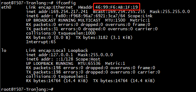
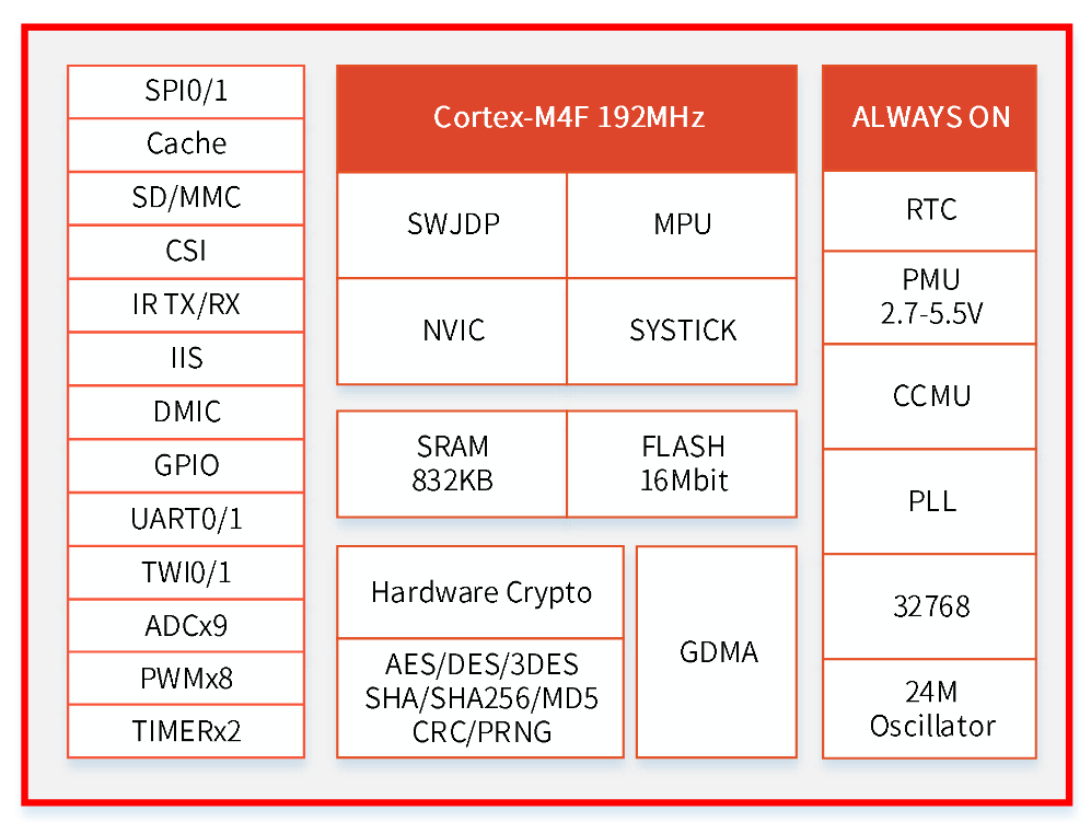
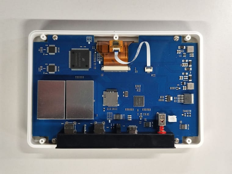
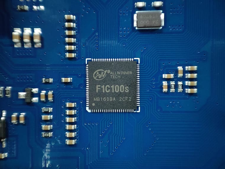
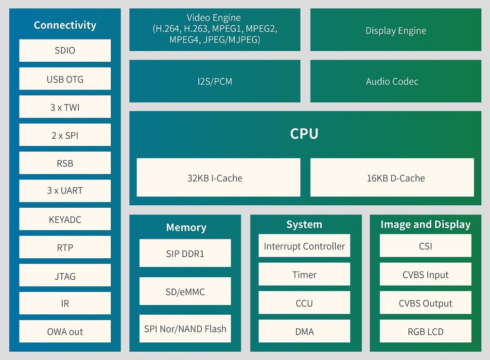
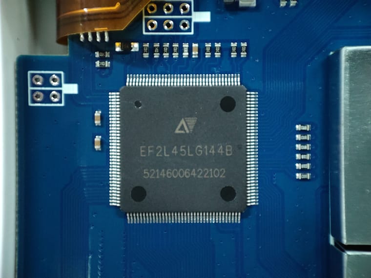
      平台: D1s+XR819S(使用外部晶振24M) TINA系统

      问题现象:

      1. xr819s驱动INT加载失败,主要异常
        [XRADIO_ERR] fw_record_read: Wait for wakeup:device is not responding.

      复现步骤:

      1. 给机器上电
      2. 等待机器启动完成
      3. 确认wifi是否正常,正常回到步骤1,异常发现xr819s驱动加载异常。

      详细log见(wifi_ng.txt)

      BusyBox v1.27.2 () built-in shell (ash)
      ------run profile file-----
       _____  _              __     _
      |_   _||_| ___  _ _   |  |   |_| ___  _ _  _ _
        | |   _ |   ||   |  |  |__ | ||   || | ||_'_|
        | |  | || | || _ |  |_____||_||_|_||___||_,_|
        |_|  |_||_|_||_|_|  Tina is Based on OpenWrt!
       ----------------------------------------------
       Tina Linux (Neptune, 5C1C9C53)
       ----------------------------------------------
      nodev   debugfs
      mount: mounting none on /sys/kernel/debug failed: Device or resource busy
      root@TinaLinux:/# dmesg
      Linux version 5.4.61 (victor@inone-server1) (riscv64-unknown-linux-gnu-gcc (C-SKY RISCV Tools V1.8.4 B20200702) 8.1.0, GNU ld (GNU Binutils) 2.32) #237 PREEMPT Mon Oct 10 07:46:01 UTC 2022
      Zone ranges:
        DMA32    [mem 0x0000000040000000-0x0000000043ffffff]
        Normal   empty
      Movable zone start for each node
      Early memory node ranges
        node   0: [mem 0x0000000040000000-0x0000000043ffffff]
      Initmem setup node 0 [mem 0x0000000040000000-0x0000000043ffffff]
      On node 0 totalpages: 16384
        DMA32 zone: 224 pages used for memmap
        DMA32 zone: 0 pages reserved
        DMA32 zone: 16384 pages, LIFO batch:3
      elf_hwcap is 0x20112d
      pcpu-alloc: s0 r0 d32768 u32768 alloc=1*32768
      pcpu-alloc: [0] 0
      Built 1 zonelists, mobility grouping on.  Total pages: 16160
      Kernel command line: ubi.mtd=sys ubi.block=0,rootfs earlyprintk=sunxi-uart,0x02500400 clk_ignore_unused initcall_debug=0 console=ttyS1,115200 loglevel=0 root=/dev/ubiblock0_5 rootfstype=squashfs init=/pseudo_init partitions=mbr@ubi0_0:boot-resource@ubi0_1:env@ubi0_2:env-redund@ubi0_3:boot@ubi0_4:rootfs@ubi0_5:rootfs_data@ubi0_6:UDISK@ubi0_7: cma=0M snum= mac_addr= wifi_mac= bt_mac= specialstr= gpt=1 androidboot.hardware=sun20iw1p1 boot_type=5 androidboot.boot_type=5 gpt=1 uboot_message=2018.07-00012-g32210268-dirty(12/22/2022-17:28:48) mbr_offset=1556480 disp_reserve=921600,0x0000000042b71000 aw-ubi-spinand.ubootblks=24 androidboot.dramsize=64
      Dentry cache hash table entries: 8192 (order: 4, 65536 bytes, linear)
      Inode-cache hash table entries: 4096 (order: 3, 32768 bytes, linear)
      Sorting __ex_table...
      mem auto-init: stack:off, heap alloc:off, heap free:off
      Memory: 57140K/65536K available (3804K kernel code, 445K rwdata, 1223K rodata, 132K init, 342K bss, 8396K reserved, 0K cma-reserved) rcu: Preemptible hierarchical RCU implementation.
              Tasks RCU enabled.
      rcu: RCU calculated value of scheduler-enlistment delay is 10 jiffies.
      NR_IRQS: 0, nr_irqs: 0, preallocated irqs: 0
      plic: mapped 200 interrupts with 1 handlers for 2 contexts.
      riscv_timer_init_dt: Registering clocksource cpuid [0] hartid [0]
      clocksource: riscv_clocksource: mask: 0xffffffffffffffff max_cycles: 0x588fe9dc0, max_idle_ns: 440795202592 ns
      sched_clock: 64 bits at 24MHz, resolution 41ns, wraps every 4398046511097ns
      riscv_timer_clockevent depends on broadcast, but no broadcast function available
      clocksource: timer: mask: 0xffffffff max_cycles: 0xffffffff, max_idle_ns: 79635851949 ns
      Calibrating delay loop (skipped), value calculated using timer frequency.. 48.00 BogoMIPS (lpj=240000)
      pid_max: default: 32768 minimum: 301
      Mount-cache hash table entries: 512 (order: 0, 4096 bytes, linear)
      Mountpoint-cache hash table entries: 512 (order: 0, 4096 bytes, linear)
      ASID allocator initialised with 65536 entries
      rcu: Hierarchical SRCU implementation.
      devtmpfs: initialized
      random: get_random_u32 called from 0xffffffe000157198 with crng_init=0
      clocksource: jiffies: mask: 0xffffffff max_cycles: 0xffffffff, max_idle_ns: 19112604462750000 ns
      futex hash table entries: 256 (order: 0, 6144 bytes, linear)
      pinctrl core: initialized pinctrl subsystem
      NET: Registered protocol family 16
      DMA: preallocated 256 KiB pool for atomic allocations
      cpuidle: using governor menu
      rtc_ccu: sunxi ccu init OK
      clock: sunxi ccu init OK
      clock: sunxi ccu init OK
      sun6i-dma 3002000.dma-controller: sunxi dma probed
      iommu: Default domain type: Translated
      sunxi iommu: irq = 4
      SCSI subsystem initialized
      usbcore: registered new interface driver usbfs
      usbcore: registered new interface driver hub
      usbcore: registered new device driver usb
      videodev: Linux video capture interface: v2.00
      Advanced Linux Sound Architecture Driver Initialized.
      pwm module init!
      g2d 5410000.g2d: Adding to iommu group 0
      G2D: rcq version initialized.major:252
      clocksource: Switched to clocksource riscv_clocksource
      sun8iw20-pinctrl pio: initialized sunXi PIO driver
      NET: Registered protocol family 2
      tcp_listen_portaddr_hash hash table entries: 256 (order: 0, 4096 bytes, linear)
      TCP established hash table entries: 512 (order: 0, 4096 bytes, linear)
      TCP bind hash table entries: 512 (order: 0, 4096 bytes, linear)
      TCP: Hash tables configured (established 512 bind 512)
      UDP hash table entries: 256 (order: 1, 8192 bytes, linear)
      UDP-Lite hash table entries: 256 (order: 1, 8192 bytes, linear)
      NET: Registered protocol family 1
      sun8iw20-pinctrl pio: pio supply vcc-pc not found, using dummy regulator
      spi spi0: spi0 supply spi not found, using dummy regulator
      sunxi_spi_resource_get()2438 - [spi0] SPI MASTER MODE
      sunxi_spi_resource_get()2485 - sample_mode:1 sample_delay:26
      sunxi_spi_clk_init()2527 - [spi0] mclk 100000000
      sunxi_spi_probe()2964 - [spi0]: driver probe succeed, base ffffffd004058000, irq 31
      workingset: timestamp_bits=62 max_order=14 bucket_order=0
      squashfs: version 4.0 (2009/01/31) Phillip Lougher
      ntfs: driver 2.1.32 [Flags: R/W].
      io scheduler mq-deadline registered
      io scheduler kyber registered
      [DISP]disp_module_init
      disp 5000000.disp: Adding to iommu group 0
      [DISP] parser_disp_init_para,line:1407:
      of_property_read fb0_width fail
      [DISP] disp_init,line:2331:
      smooth display screen:0 type:1 mode:4
      display_fb_request,fb_id:0
      Freeing logo buffer memory: 900K
      disp_al_manager_apply ouput_type:1
      [DISP] lcd_clk_config,line:774:
      disp 0, clk: pll(480000000),clk(480000000),dclk(80000000) dsi_rate(80000000)
           clk real:pll(480000000),clk(480000000),dclk(120000000) dsi_rate(150000000)
      sun8iw20-pinctrl pio: pio supply vcc-pd not found, using dummy regulator
      [DISP]disp_module_init finish
      sunxi_sid_init()563 - insmod ok
      pwm-regulator: supplied by regulator-dummy
      sun8iw20-pinctrl pio: pio supply vcc-pg not found, using dummy regulator
      uart uart1: uart1 supply uart not found, using dummy regulator
      uart1: ttyS1 at MMIO 0x2500400 (irq = 19, base_baud = 1500000) is a SUNXI
      sw_console_setup()1807 - console setup baud 115200 parity n bits 8, flow n
      printk: console [ttyS1] enabled
      uart uart3: uart3 supply uart not found, using dummy regulator
      uart3: ttyS3 at MMIO 0x2500c00 (irq = 21, base_baud = 1500000) is a SUNXI
      sun8iw20-pinctrl pio: pio supply vcc-pb not found, using dummy regulator
      uart uart5: uart5 supply uart not found, using dummy regulator
      uart5: ttyS5 at MMIO 0x2501400 (irq = 23, base_baud = 1500000) is a SUNXI
      misc dump reg init
      sunxi-rfkill soc@3000000:rfkill@0: module version: v1.0.9
      sunxi-rfkill soc@3000000:rfkill@0: get gpio chip_en failed
      sunxi-rfkill soc@3000000:rfkill@0: get gpio power_en failed
      sunxi-rfkill soc@3000000:rfkill@0: wlan_busnum (1)
      sunxi-rfkill soc@3000000:rfkill@0: Missing wlan_power.
      sunxi-rfkill soc@3000000:rfkill@0: wlan clock[0] (32k-fanout1)
      sunxi-rfkill soc@3000000:rfkill@0: wlan_regon gpio=131 assert=1
      sun8iw20-pinctrl pio: pio supply vcc-pe not found, using dummy regulator
      sunxi-rfkill soc@3000000:rfkill@0: wlan_hostwake gpio=202 assert=1
      sunxi-rfkill soc@3000000:rfkill@0: wakeup source is enabled
      sunxi-rfkill soc@3000000:rfkill@0: Missing bt_power.
      sunxi-rfkill soc@3000000:rfkill@0: bt clock[0] (32k-fanout1)
      sunxi-rfkill soc@3000000:rfkill@0: bt_rst gpio=210 assert=0
      [ADDR_MGT] addr_mgt_probe: module version: v1.0.11
      [ADDR_MGT] addr_mgt_probe: success.
      sunxi-spinand: AW SPINand MTD Layer Version: 2.3 20211223
      sunxi-spinand-phy: AW SPINand Phy Layer Version: 1.10 20200306
      sunxi-spinand-phy: not detect any munufacture from id table
      sunxi-spinand-phy: get spi-nand Model from fdt fail
      sunxi-spinand-phy: get phy info from fdt fail
      sunxi-spinand-phy: not detect munufacture from fdt
      sunxi-spinand-phy: detect munufacture from id table: Mxic
      sunxi-spinand-phy: detect spinand id: ffff12c2 ffffffff
      sunxi-spinand-phy: ========== arch info ==========
      sunxi-spinand-phy: Model:               MX35LF1GE4AB
      sunxi-spinand-phy: Munufacture:         Mxic
      sunxi-spinand-phy: DieCntPerChip:       1
      sunxi-spinand-phy: BlkCntPerDie:        1024
      sunxi-spinand-phy: PageCntPerBlk:       64
      sunxi-spinand-phy: SectCntPerPage:      4
      sunxi-spinand-phy: OobSizePerPage:      64
      sunxi-spinand-phy: BadBlockFlag:        0x1
      sunxi-spinand-phy: OperationOpt:        0x7
      sunxi-spinand-phy: MaxEraseTimes:       65000
      sunxi-spinand-phy: EccFlag:             0x2
      sunxi-spinand-phy: EccType:             4
      sunxi-spinand-phy: EccProtectedType:    3
      sunxi-spinand-phy: ========================================
      sunxi-spinand-phy:
      sunxi-spinand-phy: ========== physical info ==========
      sunxi-spinand-phy: TotalSize:    128 M
      sunxi-spinand-phy: SectorSize:   512 B
      sunxi-spinand-phy: PageSize:     2 K
      sunxi-spinand-phy: BlockSize:    128 K
      sunxi-spinand-phy: OOBSize:      64 B
      sunxi-spinand-phy: ========================================
      sunxi-spinand-phy:
      sunxi-spinand-phy: ========== logical info ==========
      sunxi-spinand-phy: TotalSize:    128 M
      sunxi-spinand-phy: SectorSize:   512 B
      sunxi-spinand-phy: PageSize:     4 K
      sunxi-spinand-phy: BlockSize:    256 K
      sunxi-spinand-phy: OOBSize:      128 B
      sunxi-spinand-phy: ========================================
      sunxi-spinand-phy: block lock register: 0x00
      sunxi-spinand-phy: feature register: 0x11
      sunxi-spinand-phy: sunxi physic nand init end
      Creating 4 MTD partitions on "sunxi_mtd_nand":
      0x000000000000-0x000000100000 : "boot0"
      0x000000100000-0x000000400000 : "uboot"
      random: fast init done
      0x000000400000-0x000000500000 : "secure_storage"
      0x000000500000-0x000008000000 : "sys"
      ehci_hcd: USB 2.0 'Enhanced' Host Controller (EHCI) Driver
      sunxi-ehci: EHCI SUNXI driver
      get ehci1-controller wakeup-source is fail.
      sunxi ehci1-controller don't init wakeup source
      [sunxi-ehci1]: probe, pdev->name: 4200000.ehci1-controller, sunxi_ehci: 0xffffffe0005c0948, 0x:ffffffd004074000, irq_no:31
      sunxi-ehci 4200000.ehci1-controller: 4200000.ehci1-controller supply drvvbus not found, using dummy regulator
      sunxi-ehci 4200000.ehci1-controller: 4200000.ehci1-controller supply hci not found, using dummy regulator
      sunxi-ehci 4200000.ehci1-controller: EHCI Host Controller
      sunxi-ehci 4200000.ehci1-controller: new USB bus registered, assigned bus number 1
      sunxi-ehci 4200000.ehci1-controller: irq 49, io mem 0x04200000
      sunxi-ehci 4200000.ehci1-controller: USB 2.0 started, EHCI 1.00
      hub 1-0:1.0: USB hub found
      hub 1-0:1.0: 1 port detected
      ohci_hcd: USB 1.1 'Open' Host Controller (OHCI) Driver
      sunxi-ohci: OHCI SUNXI driver
      get ohci1-controller wakeup-source is fail.
      sunxi ohci1-controller don't init wakeup source
      [sunxi-ohci1]: probe, pdev->name: 4200400.ohci1-controller, sunxi_ohci: 0xffffffe0005c0d10
      sunxi-ohci 4200400.ohci1-controller: 4200400.ohci1-controller supply drvvbus not found, using dummy regulator
      sunxi-ohci 4200400.ohci1-controller: 4200400.ohci1-controller supply hci not found, using dummy regulator
      sunxi-ohci 4200400.ohci1-controller: OHCI Host Controller
      sunxi-ohci 4200400.ohci1-controller: new USB bus registered, assigned bus number 2
      sunxi-ohci 4200400.ohci1-controller: irq 50, io mem 0x04200400
      hub 2-0:1.0: USB hub found
      hub 2-0:1.0: 1 port detected
      sunxi-rtc 7090000.rtc: errata__fix_alarm_day_reg_default_value(): ALARM0_DAY_REG=0, set it to 1
      sunxi-rtc 7090000.rtc: Warning: Using internal RC 16M clock source. Time may be inaccurate!
      sunxi-rtc 7090000.rtc: Warning: Using internal RC 16M clock source. Time may be inaccurate!
      sunxi-rtc 7090000.rtc: Warning: Using internal RC 16M clock source. Time may be inaccurate!
      sunxi-rtc 7090000.rtc: registered as rtc0
      sunxi-rtc 7090000.rtc: Warning: Using internal RC 16M clock source. Time may be inaccurate!
      sunxi-rtc 7090000.rtc: setting system clock to 1970-01-01T00:00:03 UTC (3)
      sunxi-rtc 7090000.rtc: sunxi rtc probed
      i2c /dev entries driver
      sunxi cedar version 1.1
      sunxi-cedar 1c0e000.ve: Adding to iommu group 0
      VE: install start!!!
      
      VE: cedar-ve the get irq is 6
      
      VE: ve_debug_proc_info:(____ptrval____), data:(____ptrval____), lock:(____ptrval____)
      
      VE: install end!!!
      
      VE: sunxi_cedar_probe
      sunxi-mmc 4021000.sdmmc: SD/MMC/SDIO Host Controller Driver(v4.25 2022-6-21 13:40)
      sunxi-mmc 4021000.sdmmc: ***ctl-spec-caps*** 8
      sunxi-mmc 4021000.sdmmc: No vmmc regulator found
      sunxi-mmc 4021000.sdmmc: No vqmmc regulator found
      sunxi-mmc 4021000.sdmmc: No vdmmc regulator found
      sunxi-mmc 4021000.sdmmc: No vd33sw regulator found
      sunxi-mmc 4021000.sdmmc: No vd18sw regulator found
      sunxi-mmc 4021000.sdmmc: No vq33sw regulator found
      sunxi-mmc 4021000.sdmmc: No vq18sw regulator found
      sunxi-mmc 4021000.sdmmc: Cann't get pin bias hs pinstate,check if needed
      sunxi-mmc 4021000.sdmmc: sdc set ios:clk 0Hz bm PP pm UP vdd 21 width 1 timing LEGACY(SDR12) dt B
      sunxi-mmc 4021000.sdmmc: no vqmmc,Check if there is regulator
      sunxi-mmc 4021000.sdmmc: sdc set ios:clk 400000Hz bm PP pm ON vdd 21 width 1 timing LEGACY(SDR12) dt B
      sunxi-mmc 4021000.sdmmc: detmode:manually by software
      sunxi-mmc 4021000.sdmmc: smc 0 p1 err, cmd 52, RTO !!
      sunxi-mmc 4021000.sdmmc: smc 0 p1 err, cmd 52, RTO !!
      sunxi-mmc 4021000.sdmmc: sdc set ios:clk 400000Hz bm PP pm ON vdd 21 width 1 timing LEGACY(SDR12) dt B
      ashmem: initialized
      exFAT: Version 1.3.0
      sunxi-mmc 4021000.sdmmc: sdc set ios:clk 400000Hz bm PP pm ON vdd 21 width 1 timing LEGACY(SDR12) dt B
      sunxi-mmc 4021000.sdmmc: smc 0 p1 err, cmd 5, RTO !!
      sunxi-mmc 4021000.sdmmc: smc 0 p1 err, cmd 5, RTO !!
      sunxi-mmc 4021000.sdmmc: smc 0 p1 err, cmd 5, RTO !!
      sunxi-mmc 4021000.sdmmc: smc 0 p1 err, cmd 5, RTO !!
      sunxi-mmc 4021000.sdmmc: sdc set ios:clk 0Hz bm PP pm OFF vdd 0 width 1 timing LEGACY(SDR12) dt B
      [AUDIOCODEC][sunxi_codec_parse_params][2437]:digital_vol:0, lineout_vol:26, mic1gain:31, mic2gain:31 pa_msleep:120, pa_level:1, pa_pwr_level:1
      
      [AUDIOCODEC][sunxi_codec_parse_params][2473]:adcdrc_cfg:0, adchpf_cfg:1, dacdrc_cfg:0, dachpf:0
      [AUDIOCODEC][sunxi_internal_codec_probe][2634]:codec probe finished
      debugfs: Directory '203034c.dummy_cpudai' with parent 'audiocodec' already present!
      [SNDCODEC][sunxi_card_init][583]:card init finished
      sunxi-codec-machine 2030340.sound: 2030000.codec <-> 203034c.dummy_cpudai mapping ok
      input: audiocodec sunxi Audio Jack as /devices/platform/soc@3000000/2030340.sound/sound/card0/input0
      [SNDCODEC][sunxi_card_dev_probe][836]:register card finished
      NET: Registered protocol family 10
      [SNDCODEC][sunxi_hs_init_work][259]:resume-->report switch
      Segment Routing with IPv6
      NET: Registered protocol family 17
      i2c-gpio soc@3000000:i2c-gpio@4: using lines 141 (SDA) and 140 (SCL)
      get ehci0-controller wakeup-source is fail.
      sunxi ehci0-controller don't init wakeup source
      [sunxi-ehci0]: probe, pdev->name: 4101000.ehci0-controller, sunxi_ehci: 0xffffffe0005c01b8, 0x:ffffffd0040ee000, irq_no:2e
      [sunxi-ehci0]: Not init ehci0
      get ohci0-controller wakeup-source is fail.
      sunxi ohci0-controller don't init wakeup source
      [sunxi-ohci0]: probe, pdev->name: 4101400.ohci0-controller, sunxi_ohci: 0xffffffe0005c0580
      [sunxi-ohci0]: Not init ohci0
      Authentication OK
      ubi0: attaching mtd3
      random: crng init done
      ubi0: scanning is finished
      ubi0: attached mtd3 (name "sys", size 123 MiB)
      ubi0: PEB size: 262144 bytes (256 KiB), LEB size: 258048 bytes
      ubi0: min./max. I/O unit sizes: 4096/4096, sub-page size 2048
      ubi0: VID header offset: 2048 (aligned 2048), data offset: 4096
      ubi0: good PEBs: 492, bad PEBs: 0, corrupted PEBs: 0
      ubi0: user volume: 8, internal volumes: 1, max. volumes count: 128
      ubi0: max/mean erase counter: 4/1, WL threshold: 4096, image sequence number: 0
      ubi0: available PEBs: 0, total reserved PEBs: 492, PEBs reserved for bad PEB handling: 20
      ubi0: background thread "ubi_bgt0d" started, PID 60
      block ubiblock0_5: created from ubi0:5(rootfs)
      otg manager soc@3000000:usbc0@0: soc@3000000:usbc0@0 supply usbc not found, using dummy regulator
      clk: Not disabling unused clocks
      ALSA device list:
        #0: audiocodec
      alloc_fd: slot 0 not NULL!
      platform regulatory.0: Direct firmware load for regulatory.db failed with error -2
      cfg80211: failed to load regulatory.db
      VFS: Mounted root (squashfs filesystem) readonly on device 254:0.
      devtmpfs: mounted
      Freeing unused kernel memory: 132K
      This architecture does not have kernel memory protection.
      Run /pseudo_init as init process
      UBIFS (ubi0:6): Mounting in unauthenticated mode
      UBIFS (ubi0:6): background thread "ubifs_bgt0_6" started, PID 85
      UBIFS (ubi0:6): recovery needed
      UBIFS (ubi0:6): recovery completed
      UBIFS (ubi0:6): UBIFS: mounted UBI device 0, volume 6, name "rootfs_data"
      UBIFS (ubi0:6): LEB size: 258048 bytes (252 KiB), min./max. I/O unit sizes: 4096 bytes/4096 bytes
      UBIFS (ubi0:6): FS size: 70705152 bytes (67 MiB, 274 LEBs), journal size 3612672 bytes (3 MiB, 14 LEBs)
      UBIFS (ubi0:6): reserved for root: 3339578 bytes (3261 KiB)
      UBIFS (ubi0:6): media format: w5/r0 (latest is w5/r0), UUID 6F06728E-F9EE-4F79-8337-A20F7745B8A1, small LPT model
      UBIFS (ubi0:7): Mounting in unauthenticated mode
      UBIFS (ubi0:7): background thread "ubifs_bgt0_7" started, PID 115
      UBIFS (ubi0:7): recovery needed
      UBIFS (ubi0:7): recovery completed
      UBIFS (ubi0:7): UBIFS: mounted UBI device 0, volume 7, name "UDISK"
      UBIFS (ubi0:7): LEB size: 258048 bytes (252 KiB), min./max. I/O unit sizes: 4096 bytes/4096 bytes
      UBIFS (ubi0:7): FS size: 2580480 bytes (2 MiB, 10 LEBs), journal size 1806337 bytes (1 MiB, 5 LEBs)
      UBIFS (ubi0:7): reserved for root: 121882 bytes (119 KiB)
      UBIFS (ubi0:7): media format: w5/r0 (latest is w5/r0), UUID 5B4008FC-7440-4B25-B0AA-BEF8B944333D, small LPT model
      
      insmod_device_driver
      
      sunxi_usb_udc 4100000.udc-controller: 4100000.udc-controller supply udc not found, using dummy regulator
      ======== XRADIO WIFI OPEN ========
      [XRADIO] Driver Label:XR_V02.25.82   Aug 19 2022 07:55:11
      [XRADIO] Allocated hw_priv @ 000000001e8f7730
      sunxi-rfkill soc@3000000:rfkill@0: bus_index: 1
      sunxi-rfkill soc@3000000:rfkill@0: wlan power on success
      sunxi-mmc 4021000.sdmmc: sdc set ios:clk 0Hz bm PP pm UP vdd 21 width 1 timing LEGACY(SDR12) dt B
      sunxi-mmc 4021000.sdmmc: no vqmmc,Check if there is regulator
      [XRADIO] Detect SDIO card 1
      sunxi-mmc 4021000.sdmmc: sdc set ios:clk 400000Hz bm PP pm ON vdd 21 width 1 timing LEGACY(SDR12) dt B
      sunxi-mmc 4021000.sdmmc: sdc set ios:clk 400000Hz bm PP pm ON vdd 21 width 1 timing LEGACY(SDR12) dt B
      sunxi-mmc 4021000.sdmmc: sdc set ios:clk 400000Hz bm PP pm ON vdd 21 width 1 timing LEGACY(SDR12) dt B
      sunxi-mmc 4021000.sdmmc: sdc set ios:clk 400000Hz bm PP pm ON vdd 21 width 1 timing SD-HS(SDR25) dt B
      sunxi-mmc 4021000.sdmmc: sdc set ios:clk 50000000Hz bm PP pm ON vdd 21 width 1 timing SD-HS(SDR25) dt B
      sunxi-mmc 4021000.sdmmc: sdc set ios:clk 50000000Hz bm PP pm ON vdd 21 width 4 timing SD-HS(SDR25) dt B
      mmc0: new high speed SDIO card at address 0001
      [SBUS] XRadio Device:sdio clk=50000000
      [XRADIO] XRADIO_HW_REV 1.1 detected.
      [XRADIO] Bootloader complete
      [XRADIO] Firmware completed.
      [WSM] Firmware Label:R0-XR_C07.08.52.65_02.65 Mar  5 2021 11:45:46
      [WSM] Efuse Flag=0x91, MAC Addr=80:74:84:02:25:93
      [XRADIO] Firmware Startup Done.
      mac80211_register_hw signal_type CFG80211_SIGNAL_TYPE_MBM
      ieee80211 phy0: Selected rate control algorithm 'minstrel_ht'
      [BH_ERR] Device cannot wakeup in 2000ms.
      ------------[ cut here ]------------
      WARNING: CPU: 0 PID: 121 at drivers/net/wireless/xr819s/wlan/bh.c:878 0xffffffdf80611720
      Modules linked in: xr819s
      CPU: 0 PID: 121 Comm: xradio_bh Not tainted 5.4.61 #237
      sepc: ffffffdf80611720 ra : ffffffdf80611720 sp : ffffffe0018ebd90
       gp : ffffffe000579dec tp : ffffffe00258c000 t0 : ffffffe00058db58
       t1 : 0000000000000063 t2 : 0000000000000002 s0 : ffffffe001849ee0
       s1 : ffffffdf8063fd3d a0 : 0000000000000028 a1 : 0000000000000000
       a2 : 0000000000000000 a3 : ffffffe00051cc00 a4 : 0000000000000000
       a5 : 0000000000000000 a6 : 0000000000000004 a7 : 0000000000000028
       s2 : 0000000000000001 s3 : 0000000000000000 s4 : 0000000000000000
       s5 : ffffffe0018ebe08 s6 : 0000000000001000 s7 : ffffffe00051fa90
       s8 : ffffffe00184a530 s9 : 0000000000000fff s10: ffffffe0018ebe00
       s11: 0000000000000002 t3 : ffffffffffffffff t4 : ffffffe00051be08
       t5 : 0000000000000001 t6 : ffffffe00058db58
      sstatus: 0000000200000120 sbadaddr: 0000000000000000 scause: 0000000000000003
      ---[ end trace 0515eeb33a71b7fa ]---
      [BH_ERR] Fatal error, exitting code=879.
      [XRADIO_ERR] fw_record_read: Wait for wakeup:device is not responding.
      [XRADIO] fw_record addr=0x7fb3dae6
      [XRADIO_ERR] fw_record_read:unkown record=0x7fb3dae6
      [XRADIO] --FW_RECORD_READ START--
      [XRADIO] Current SCHED=0
      [XRADIO] 0x00,0x00,0x00,0x00 0x00,0x00,0x00,0x00
      [XRADIO] 0x00,0x00,0x00,0x00 0x00,0x00,0x00,0x00
      [XRADIO] 0x00,0x00,0x00,0x00 0x00,0x00,0x00,0x00
      [XRADIO] 0x00,0x00,0x00,0x00 0x00,0x00,0x00,0x00
      [XRADIO] Current cmds=0
      [XRADIO] 0x0000,0x0000,0x0000,0x0000
      [XRADIO] 0x0000,0x0000,0x0000,0x0000
      [XRADIO] 0x0000,0x0000,0x0000,0x0000
      [XRADIO] 0x0000,0x0000,0x0000,0x0000
      [XRADIO] Current frames=0
      [XRADIO] 0x00000000,0x00000000,0x00000000,0x00000000
      [XRADIO] 0x00000000,0x00000000,0x00000000,0x00000000
      [XRADIO] 0x00000000,0x00000000,0x00000000,0x00000000
      [XRADIO] 0x00000000,0x00000000,0x00000000,0x00000000
      [XRADIO] 0x00000000,0x00000000,0x00000000,0x00000000
      [XRADIO] 0x00000000,0x00000000,0x00000000,0x00000000
      [XRADIO] 0x00000000,0x00000000,0x00000000,0x00000000
      [XRADIO] 0x00000000,0x00000000,0x00000000,0x00000000
      [XRADIO] Current Fiqs=0
      [XRADIO] 0x00000000,0x00000000,0x00000000,0x00000000
      [XRADIO] 0x00000000,0x00000000,0x00000000,0x00000000
      [XRADIO] 0x00000000,0x00000000,0x00000000,0x00000000
      [XRADIO] 0x00000000,0x00000000,0x00000000,0x00000000
      [XRADIO] 0x00000000,0x00000000,0x00000000,0x00000000
      [XRADIO] 0x00000000,0x00000000,0x00000000,0x00000000
      [XRADIO] 0x00000000,0x00000000,0x00000000,0x00000000
      [XRADIO] 0x00000000,0x00000000,0x00000000,0x00000000
      [XRADIO] Current PC=0x00000000
      [XRADIO] Current Timer=0
      [XRADIO] 0x00000000,0x00000000,0x00000000,0x00000000
      [XRADIO] 0x00000000,0x00000000,0x00000000,0x00000000
      [XRADIO] 0x00000000,0x00000000,0x00000000,0x00000000
      [XRADIO] 0x00000000,0x00000000,0x00000000,0x00000000
      [XRADIO] 0x00000000,0x00000000,0x00000000,0x00000000
      [XRADIO] 0x00000000,0x00000000,0x00000000,0x00000000
      [XRADIO] 0x00000000,0x00000000,0x00000000,0x00000000
      [XRADIO] 0x00000000,0x00000000,0x00000000,0x00000000
      [XRADIO] --FW_RECORD_READ END--
      [WSM_ERR] ***CMD timeout!>>> 0x0009 (820), cmd_ptr=00000000405ef7e2, buf_use=0,bh_state=879
      ------------[ cut here ]------------
      WARNING: CPU: 0 PID: 122 at drivers/net/wireless/xr819s/wlan/sta.c:1920 0xffffffdf806189a8
      Modules linked in: xr819s
      CPU: 0 PID: 122 Comm: wpa_supplicant Tainted: G        W         5.4.61 #237
      sepc: ffffffdf806189a8 ra : ffffffdf806189a2 sp : ffffffe00180baa0
       gp : ffffffe000579dec tp : ffffffe0026ac000 t0 : ffffffe00058ec40
       t1 : 0000000000000063 t2 : 0000000000000000 s0 : ffffffe001849ee0
       s1 : 0000000000000001 a0 : ffffffffffffff92 a1 : 0000000000000003
       a2 : 0000000000000001 a3 : ffffffe00184a530 a4 : 0000000000000000
       a5 : 0000000000000000 a6 : 0000000000000004 a7 : 000000000000005b
       s2 : ffffffdf8063fd3a s3 : ffffffe00184f740 s4 : ffffffe001800000
       s5 : ffffffe001848900 s6 : 0000000000000000 s7 : 0000000000000000
       s8 : 0000000000000000 s9 : 0000000000000007 s10: 00000000000de3f0
       s11: 0000000000000000 t3 : ffffffffffffffff t4 : ffffffe00051be08
       t5 : 0000000000000001 t6 : ffffffe00058ec3b
      sstatus: 0000000200000120 sbadaddr: 0000000000000000 scause: 0000000000000003
      ---[ end trace 0515eeb33a71b7fb ]---
      ------------[ cut here ]------------
      WARNING: CPU: 0 PID: 122 at drivers/net/wireless/xr819s/wlan/sta.c:168 0xffffffdf80618ba0
      Modules linked in: xr819s
      CPU: 0 PID: 122 Comm: wpa_supplicant Tainted: G        W         5.4.61 #237
      sepc: ffffffdf80618ba0 ra : ffffffdf80618b9c sp : ffffffe00180bb20
       gp : ffffffe000579dec tp : ffffffe0026ac000 t0 : ffffffe00058ec40
       t1 : ffffffe00008e06e t2 : 0000000000000000 s0 : 0000000000000001
       s1 : ffffffe00184a3b0 a0 : 0000000000000001 a1 : 0000000000000050
       a2 : 00000000000003fc a3 : 000000000000bf0c a4 : 0000000000000000
       a5 : 0000000000000000 a6 : ffffffe003fa24e0 a7 : 00000000000051f3
       s2 : ffffffdf806422d0 s3 : ffffffdf8063fd3a s4 : ffffffe001800000
       s5 : ffffffe001848900 s6 : 0000000000000000 s7 : 0000000000000000
       s8 : 0000000000000000 s9 : 0000000000000007 s10: 00000000000de3f0
       s11: 0000000000000000 t3 : ffffffffffffffff t4 : ffffffe00051be08
       t5 : 0000000000000001 t6 : ffffffe00058ec3b
      sstatus: 0000000200000120 sbadaddr: 0000000000000000 scause: 0000000000000003
      ---[ end trace 0515eeb33a71b7fc ]---
      [STA_ERR] xradio_start, xradio_setup_mac failed(1)
      file system registered
      configfs-gadget 4100000.udc-controller: failed to start g1: -19
      read descriptors
      read strings
      sunxi_set_cur_vol_work()489 WARN: get power supply failed
      android_work: sent uevent USB_STATE=CONNECTED
      configfs-gadget gadget: high-speed config #1: c
      android_work: sent uevent USB_STATE=CONFIGURED
      [XRADIO_ERR] fw_record_read: Wait for wakeup:device is not responding.
      [XRADIO] fw_record addr=0x7fb3dae6
      [XRADIO_ERR] fw_record_read:unkown record=0x7fb3dae6
      [XRADIO] --FW_RECORD_READ START--
      [XRADIO] Current SCHED=0
      [XRADIO] 0x00,0x00,0x00,0x00 0x00,0x00,0x00,0x00
      [XRADIO] 0x00,0x00,0x00,0x00 0x00,0x00,0x00,0x00
      [XRADIO] 0x00,0x00,0x00,0x00 0x00,0x00,0x00,0x00
      [XRADIO] 0x00,0x00,0x00,0x00 0x00,0x00,0x00,0x00
      [XRADIO] Current cmds=0
      [XRADIO] 0x0000,0x0000,0x0000,0x0000
      [XRADIO] 0x0000,0x0000,0x0000,0x0000
      [XRADIO] 0x0000,0x0000,0x0000,0x0000
      [XRADIO] 0x0000,0x0000,0x0000,0x0000
      [XRADIO] Current frames=0
      [XRADIO] 0x00000000,0x00000000,0x00000000,0x00000000
      [XRADIO] 0x00000000,0x00000000,0x00000000,0x00000000
      [XRADIO] 0x00000000,0x00000000,0x00000000,0x00000000
      [XRADIO] 0x00000000,0x00000000,0x00000000,0x00000000
      [XRADIO] 0x00000000,0x00000000,0x00000000,0x00000000
      [XRADIO] 0x00000000,0x00000000,0x00000000,0x00000000
      [XRADIO] 0x00000000,0x00000000,0x00000000,0x00000000
      [XRADIO] 0x00000000,0x00000000,0x00000000,0x00000000
      [XRADIO] Current Fiqs=0
      [XRADIO] 0x00000000,0x00000000,0x00000000,0x00000000
      [XRADIO] 0x00000000,0x00000000,0x00000000,0x00000000
      [XRADIO] 0x00000000,0x00000000,0x00000000,0x00000000
      [XRADIO] 0x00000000,0x00000000,0x00000000,0x00000000
      [XRADIO] 0x00000000,0x00000000,0x00000000,0x00000000
      [XRADIO] 0x00000000,0x00000000,0x00000000,0x00000000
      [XRADIO] 0x00000000,0x00000000,0x00000000,0x00000000
      [XRADIO] 0x00000000,0x00000000,0x00000000,0x00000000
      [XRADIO] Current PC=0x00000000
      [XRADIO] Current Timer=0
      [XRADIO] 0x00000000,0x00000000,0x00000000,0x00000000
      [XRADIO] 0x00000000,0x00000000,0x00000000,0x00000000
      [XRADIO] 0x00000000,0x00000000,0x00000000,0x00000000
      [XRADIO] 0x00000000,0x00000000,0x00000000,0x00000000
      [XRADIO] 0x00000000,0x00000000,0x00000000,0x00000000
      [XRADIO] 0x00000000,0x00000000,0x00000000,0x00000000
      [XRADIO] 0x00000000,0x00000000,0x00000000,0x00000000
      [XRADIO] 0x00000000,0x00000000,0x00000000,0x00000000
      [XRADIO] --FW_RECORD_READ END--
      [WSM_ERR] wsm_upper_restart
      [WSM_WRN] Wait for scan complete!
      [WSM_WRN] wsm_upper_restart schedule restart_work!
      [XRADIO] xradio_restart_work
      [XRADIO] xradio_core_reinit 992!
      [WSM_ERR] bh_error=1, wsm_unlock_tx is unsafe
      sunxi-rfkill soc@3000000:rfkill@0: wlan power off success
      [XRADIO] Remove SDIO card 1
      sunxi-mmc 4021000.sdmmc: smc 0 p1 err, cmd 7, RTO !!
      sunxi-mmc 4021000.sdmmc: smc 0 p1 err, cmd 7, RTO !!
      sunxi-mmc 4021000.sdmmc: smc 0 p1 err, cmd 7, RTO !!
      sunxi-mmc 4021000.sdmmc: smc 0 p1 err, cmd 7, RTO !!
      mmc0: card 0001 removed
      sunxi-mmc 4021000.sdmmc: sdc set ios:clk 0Hz bm PP pm OFF vdd 0 width 1 timing LEGACY(SDR12) dt B
      sunxi-mmc 4021000.sdmmc: sdc set ios:clk 0Hz bm PP pm UP vdd 21 width 1 timing LEGACY(SDR12) dt B
      sunxi-mmc 4021000.sdmmc: no vqmmc,Check if there is regulator
      sunxi-mmc 4021000.sdmmc: sdc set ios:clk 400000Hz bm PP pm ON vdd 21 width 1 timing LEGACY(SDR12) dt B
      sunxi-rfkill soc@3000000:rfkill@0: bus_index: 1
      sunxi-mmc 4021000.sdmmc: smc 0 p1 err, cmd 52, RTO !!
      sunxi-mmc 4021000.sdmmc: smc 0 p1 err, cmd 52, RTO !!
      sunxi-mmc 4021000.sdmmc: sdc set ios:clk 400000Hz bm PP pm ON vdd 21 width 1 timing LEGACY(SDR12) dt B
      sunxi-mmc 4021000.sdmmc: sdc set ios:clk 400000Hz bm PP pm ON vdd 21 width 1 timing LEGACY(SDR12) dt B
      sunxi-mmc 4021000.sdmmc: smc 0 p1 err, cmd 5, RTO !!
      sunxi-mmc 4021000.sdmmc: smc 0 p1 err, cmd 5, RTO !!
      sunxi-mmc 4021000.sdmmc: smc 0 p1 err, cmd 5, RTO !!
      sunxi-mmc 4021000.sdmmc: smc 0 p1 err, cmd 5, RTO !!
      sunxi-mmc 4021000.sdmmc: sdc set ios:clk 0Hz bm PP pm OFF vdd 0 width 1 timing LEGACY(SDR12) dt B
      sunxi-rfkill soc@3000000:rfkill@0: wlan power on success
      [XRADIO] Detect SDIO card 1
      sunxi-mmc 4021000.sdmmc: sdc set ios:clk 0Hz bm PP pm UP vdd 21 width 1 timing LEGACY(SDR12) dt B
      sunxi-mmc 4021000.sdmmc: no vqmmc,Check if there is regulator
      sunxi-mmc 4021000.sdmmc: sdc set ios:clk 400000Hz bm PP pm ON vdd 21 width 1 timing LEGACY(SDR12) dt B
      sunxi-mmc 4021000.sdmmc: sdc set ios:clk 400000Hz bm PP pm ON vdd 21 width 1 timing LEGACY(SDR12) dt B
      sunxi-mmc 4021000.sdmmc: sdc set ios:clk 400000Hz bm PP pm ON vdd 21 width 1 timing LEGACY(SDR12) dt B
      sunxi-mmc 4021000.sdmmc: sdc set ios:clk 400000Hz bm PP pm ON vdd 21 width 1 timing SD-HS(SDR25) dt B
      sunxi-mmc 4021000.sdmmc: sdc set ios:clk 50000000Hz bm PP pm ON vdd 21 width 1 timing SD-HS(SDR25) dt B
      sunxi-mmc 4021000.sdmmc: sdc set ios:clk 50000000Hz bm PP pm ON vdd 21 width 4 timing SD-HS(SDR25) dt B
      mmc0: new high speed SDIO card at address 0001
      [SBUS] XRadio Device:sdio clk=50000000
      [XRADIO] XRADIO_HW_REV 1.1 detected.
      [XRADIO] Bootloader complete
      [XRADIO] Firmware completed.
      [WSM] Firmware Label:R0-XR_C07.08.52.65_02.65 Mar  5 2021 11:45:46
      [WSM] Efuse Flag=0x91, MAC Addr=80:74:84:02:25:93
      [XRADIO] xradio_core_reinit:Firmware Startup Done.
      ieee80211 phy0: Hardware restart was requested
      [XRADIO] xradio_core_reinit end!
      
      rmmod_device_driver
      
      rmmod_device_driver()222 WARN: get power supply failed
      
      insmod_device_driver
      
      android_work: sent uevent USB_STATE=DISCONNECTED
      sunxi_set_cur_vol_work()489 WARN: get power supply failed
      android_work: sent uevent USB_STATE=CONNECTED
      configfs-gadget gadget: high-speed config #1: c
      android_work: sent uevent USB_STATE=CONFIGURED
      [SNDCODEC][sunxi_card_hw_params][620]:stream_flag: 0
      

      wifi_ng.txt

      发布在 其它全志芯片讨论区
      zznzzn
      zznzzn
    • 搬运一个大佬做的T113-S3裸机IAR工程,有bootloader和led闪烁demo

      本文转自坑网:https://whycan.com/t_9627.html
      作者@zengyi703

      本人喜欢折腾
      本贴给喜欢裸机开发的人,提供一个思路。
      不欢迎上来就讨论裸机无用、裸机麻烦、嘲笑只会用现成IDE不研究GCC和系统的人,请绕行。
      本人也是初次用这些,程序难免存在一些问题和不懂的地方,欢迎一块讨论。

      一、IAR工程下的bootloader

      iar_bootloader\project\bootloader\iar目录下面有IAR工程。可以用jlink仿真,可以烧写到spinor(W25Q256)。

      1.此bootloader是将awboot移植(抄袭)到了IAR下面,做了魔改,用来支持spinor flash(因为手里只有spinor flash),启动裸机程序。

      2.这个bootloader含有t113-s3芯片的加载头,会初始化led,uart,clk,ddr,spi等外设。芯片上电从spi flash启动时,T113-S3内部的BROM会识别加载头,并将bootloader程序加载到T113-S3的内部SRAM(0x00020000),并运行。然后bootloader会读取spinor flash里面(0x00100000-0x00200000)的内容到DDR(0x40000000),并跳转到DDR运行。所以裸机程序需要烧写到spinor flash的(0x00100000-0x00200000)处。

      /* Boot head information for BROM */
      b __iar_program_start        ;DCD 0xEA000016
      DCB 'e', 'G', 'O', 'N', '.', 'B', 'T', '0'
      DCD 0x12345678               /* checksum */
      DCD 20000                        /* spl size:little large then .bin*/
      DCD 0x30                          /* boot header size */
      DCD 0x30303033               /* boot header version */
      DCD 0x00020000               /* return value */
      DCD 0x00028000               /* run address */
      DCD 0x0                           /* eGON version */
      DCB 0x00, 0x00, 0x00, 0x00   /* platform information - 8byte */
      

      3.此bootloader用IAR编译完会生成bootloader.bin,然后需要使用mksunxi.exe,把.bin文件的大小信息添加到加载头。

      mksunxi.exe bootloader.bin
      

      4.然后将带有大小信息的bootloader.bin,烧写到spinor flash的0x00000000处。

      xfel.exe spinor write 0x0 bootloader.bin
      

      5.重新启动,串口会打印信息,串口使用的是PB4,PB5引脚,波特率115200.

      ------BootLoader Info---------------------
      BootLoader spinor memory map:
        AWBoot:   0x00000000-0x00010000 64KB
        User Bin: 0x00100000-0x00200000 1MB
      BootLoader sdram memory map:
        Bare ROM: 0x40000000-0x40100000 1MB
        Bare RAM: 0x40100000-0x40200000 1MB
      ------BootLoader Start--------------------
      DRAM: TYPE = DDR3, CLK = 792 MHz
      DRAM: SIZE = 128MB
      CLK: PLL_CPUX = 1200MHz
      CLK: PLL_PERI(2X) = 1200MHz
      CLK: PLL_PERI(1X) = 600MHz
      CLK: PLL_PERI(800) = 800MHz
      CLK: PLL_DDR = 1584MHz
      SPI: CLKIN = 600MHz, DIV = 3, N = 1, M = 3
      SPI: CLOCK ACTUAL = 100MHz MCLK = 200MHz
      DMA: USE CHANNEL 0
      SPI-NOR: MFR:0xEF DEV:0x4019
      SPI NOR: READ USER BIN TIME:20986uS
      ------BootLoader Jump Successed-----------
      
      bootloader使用的的spinor空间在0x00000000-0x00010000预留了64KB。
      裸机程序使用的spinor空间在0x00100000-0x00200000预留了1MB。
      

      二、IAR下的LED工程

      1.编译运行

      iar_project\project\1_demo\iar目录下面有IAR工程,可以用Jlink连接板子进行仿真,也可以编译完成后生成一个demo.bin文件,烧写到spinor(0x00100000)。链接地址是0x40000000

      可以用如下命令烧写到spinor

      xfel.exe spinor write 0x100000 demo.bin`命令烧写到spinor.
      

      重启后,会发现bootloader已经将led程序加载并运行起来,闪灯。

      总的来说,就是先烧写bootloader到spinor的0x0处,再烧写demo.bin到spinor的0x00100000处
      这样重启后就会先运行bootloader,再运行裸机程序demo.bin。

      完整工程分享到这里:(链到哇酷自行下载)

      t113-s3.rar

      微信图片_20230407101953.jpg

      发布在 其它全志芯片讨论区
      zznzzn
      zznzzn
    • 回复: 支持DDR4的芯片(如H616)想用DDR3时引脚该怎么接

      @bayche 主要是感觉资料也没说明啊,像是data sheet和user manual都没找到的样子

      发布在 其它全志芯片讨论区
      zznzzn
      zznzzn
    • 支持DDR4的芯片(如H616)想用DDR3时引脚该怎么接

      想问一下这种支持DDR4的芯片(如H616)想用DDR3时引脚该怎么接呢?

      QQ图20230406083617.png

      之前一直找资料也没找到 是按DDR4的SA14为SWE的复用这样看的吗?(图中是我还没研究明白 暂时接一下)

      发布在 其它全志芯片讨论区
      zznzzn
      zznzzn
    • 启动系统上电一会,就会重新启动一次

      系统上电一会,就会重新启动一次

      QQ图片20230403111030.png

      QQ图片20230403111037.png

      应该输入什么命令来关闭这个自动boot

      QQ图片20230403111042.png

      发布在 其它全志芯片讨论区
      zznzzn
      zznzzn
    • 查看中断驱动名称不显示

      如图,请问下查看中断驱动名称不显示,是啥原因

      20230330092416.png

      发布在 MR Series
      zznzzn
      zznzzn
    • 回复: 851可以通过USB将camera 搞到电脑上显示吗?也就是uvc,但是demo里的eis找不到在哪里打开

      @haaland
      目测depend on的选项没开,依赖没有补全

      发布在 V Series
      zznzzn
      zznzzn
    • xr32f429开发环境搭建

      XR32是全志科技的一款MCU芯片,基本参数如下所示:
      2416267-20230228185228839-1173685325.png

      环境的搭建首先是下载芯片对应的资料和手册(QQ群723687715)软硬件资料

      官网工具下载:注册全志服务平台(https://open.allwinnertech.com/#/devtool?menuID=37)

      2416267-20230228185745553-920478778.png

      下载无线连接工具和无线MCU 工具

      2416267-20230228185934373-1379615748.png

      资料下载后下载芯片的SDK包:https://gitee.com/GloomyGhost/xr32-sdk

      2416267-20230228190123846-813042283.png

      然后在linux下根据SDK包中的帮助文档进行开发环境的配置

      2416267-20230228190308955-2108186564.png

      打开终端根据Readme文档的## Install necessary packages说明进行包的安装(每一个都需要安装)

      2416267-20230228190505617-722336380.png

      安装完成之后在下载的SDK包中运如sh文件

      2416267-20230228190721433-1160079457.png

      正常运行的结果如下所示:

       1 guy@guy-X9Ti:~/XR32/xr32-sdk(只读)$ ./setup_toolchain.sh 
       2 =======================Setup Toolchain=======================
       3 --2023-02-28 19:07:29--  https://launchpad.net/gcc-arm-embedded/4.9/4.9-2015-q2-update/+download/gcc-arm-none-eabi-4_9-2015q2-20150609-linux.tar.bz2
       4 正在解析主机 launchpad.net (launchpad.net)... 185.125.189.222, 185.125.189.223, 2620:2d:4000:1001::8004, ...
       5 正在连接 launchpad.net (launchpad.net)|185.125.189.222|:443... 已连接。
       6 已发出 HTTP 请求,正在等待回应... 303 See Other
       7 位置:https://launchpadlibrarian.net/209776202/gcc-arm-none-eabi-4_9-2015q2-20150609-linux.tar.bz2 [跟随至新的 URL]
       8 --2023-02-28 19:07:30--  https://launchpadlibrarian.net/209776202/gcc-arm-none-eabi-4_9-2015q2-20150609-linux.tar.bz2
       9 正在解析主机 launchpadlibrarian.net (launchpadlibrarian.net)... 185.125.189.228, 185.125.189.229, 2620:2d:4000:1001::8007, ...
      10 正在连接 launchpadlibrarian.net (launchpadlibrarian.net)|185.125.189.228|:443... 已连接。
      11 已发出 HTTP 请求,正在等待回应... 200 OK
      12 长度: 73684786 (70M) [application/x-tar]
      13 正在保存至: ‘gcc-arm-none-eabi-4_9-2015q2-20150609-linux.tar.bz2’
      14 
      15 gcc-arm-none-eabi-4_9-2015q2-201 100%[==========================================================>]  70.27M  2.63MB/s    用时 29s   
      16 
      17 2023-02-28 19:08:01 (2.39 MB/s) - 已保存 ‘gcc-arm-none-eabi-4_9-2015q2-20150609-linux.tar.bz2’ [73684786/73684786])
      18 
      19 =======================Unarchive Toolchain=======================
      20 =======================Add Toolchain=======================
      21 =======================Add Toolchain path=======================
      22 =======================Set Tools=======================
      23 =======================ALL Done!=======================
      24 guy@guy-X9Ti:~/XR32/xr32-sdk(只读)$ 
      

      安装完成之后需要代码进行编译,直接用SDK中的案例代码

      2416267-20230228191034151-1051830954.png

      字节修改在while中需要执行的动作,最简单的打印一条日志到串口中,在gcc目录中打开终端执行make build

      2416267-20230228191314105-1283273064.png

      执行成功的话最终的结果如下:

      2416267-20230228191413714-1494096120.png

      编译完成之后在如下文件夹中会生成固件

      2416267-20230228191536282-1246115496.png

      编译完成之后就是代码的下载:配置后串口的参数

      2416267-20230228191807005-1769908443.png

      将生成的固件放到当前文件夹中,链接好串口线,将开发板的PB03引脚拉低,然后将PB02引脚拉底,然后按下复位键,松开复位键后拉高PB02,然后开发板进入升级模式(芯片没有代码的话直接下载)

      终端执行如下操作:
      2416267-20230228192609426-336857266.png

      运行过程如下:

       1 guy@guy-X9Ti:~/XR32/xradio_wireless_mcu_tools_package_v1.0.4/xradio_phoenixMC_v3.1.21014b-p1$ sudo ./phoenixMC 
       2 
       3 Version: v1.2.00815b(by notebook)
       4 phoenixMC_u -A [debug flash address]  (default: 0x00000000)
       5 phoenixMC_u -b [baud rate]  (default: 921600)
       6 phoenixMC_u -B [flash debug bin file for write]  (default: a.bin)
       7 phoenixMC_u -c [com dev] (default: /dev/ttyUSB0)
       8 phoenixMC_u -C [config file] (default: ./settings.ini)
       9 phoenixMC_u -d [debug log level]  (default: 0)
      10 phoenixMC_u -D [debug flash mode]  (default: n=NULL)
      11 phoenixMC_u -e [enable etf image]  (default: 0)
      12 phoenixMC_u -f [enable flash compat]  (default: 1)
      13 phoenixMC_u -g [enable combine images]
      14 phoenixMC_u -G [combine image path]  (default: combine_image.cimg)
      15 phoenixMC_u -h [help msg]
      16 phoenixMC_u -i [wlan image path]  (default: xr-system.img)
      17 phoenixMC_u -I [ETF image path]  (default: xr-system_etf.img)
      18 phoenixMC_u -l [log file path]   (default: ./log/log.txt)
      19 phoenixMC_u -L [debug flash length]   (default: 0x00000200)
      20 phoenixMC_u -r [read and check after write]  (default: 0)
      21 phoenixMC_u -s [show image info]
      22 phoenixMC_u -u [update changed blocks only]  (default: 1)
      23 phoenixMC_u -v [show version]
      24 
      25 When it's upgrading, input 'stop' to stop it if you need.
      26 --------------SETTING--------------
      27 COM:/dev/ttyUSB0
      28 Baud:921600
      29 Log path:./log/log.txt
      30 Log level:0
      31 Image path:./xr_system.img
      32 ETF image path:./xr_system_etf.img
      33 Read and check:NO
      34 Update change only:YES
      35 Program ETF image:NO
      36 Use flash compat:YES
      37 
      38 *************************************************
      39                firmware information              
      40 *************************************************
      41 *******************************************************************************************************************
      42 bin version: 3
      43 bin count: 3
      44 No.     ID         sram_offs     data_size     next_section     attribute     private
      45  1      0xA5FF5A00       0x00067000     0x00007570     0x00008000     0x00000001     0xFFFFFFFFFFFFFFFFFFFFFFFF
      46  2      0xA5FE5A01       0x00010000     0x0000B384     0x00053000     0x00000001     0xFFFFFFFFFFFFFFFFFFFFFFFF
      47  3      0xA5F75A08       0x60000000     0x00000000     0xFFFFFFFF     0x00000001     0xFFFFFFFFFFFFFFFFFFFFFFFF
      48 *******************************************************************************************************************
      49 
      50 not Combined image!!
      51 3%: Opening com...
      52 10%: Checking the 1 block,total 5 block(s)...
      53 10%: Erasing the 1 block,total 5 block(s)...
      54 14%: Writing the 1 block,total 5 block(s)...
      55 26%: Checking the 2 block,total 5 block(s)...
      56 26%: Erasing the 2 block,total 5 block(s)...
      57 30%: Writing the 2 block,total 5 block(s)...
      58 42%: Checking the 3 block,total 5 block(s)...
      59 58%: Checking the 4 block,total 5 block(s)...
      60 74%: Checking the 5 block,total 5 block(s)...
      61 90%: Checking rest data of 64k...
      62 guy@guy-X9Ti:~/XR32/xradio_wireless_mcu_tools_package_v1.0.4/xradio_phoenixMC_v3.1.21014b-p1$ 


      下载完成之后复位开发板,打开串口查看打印的信息

      2416267-20230228192846760-590496307.png

      到此基本环境搭建完成

      发布在 Wireless & Analog Series
      zznzzn
      zznzzn
    • 国产工业CPU平台,米尔基于全志T507-H开发板的实时性分析与测试

      原文链接:https://mp.weixin.qq.com/s/tGGlo9IILN9Yw7J094cmgg

      全志T5系列是一个高性能四核 CortexTM–A53 处理器,适用于新一代汽车市场。T5系列符合汽车 AEC – Q100 测试要求。该芯片集成四核 CortexTM–A53 CPU、G31MP2 GPU、32 位 DDR3/LPDDR3/DDR4/LRDDR4 动态随机存储器。

      MYC-YT507H核心板基于T507-H处理器研制,具有丰富的接口资源, 拥有良好的软件开发环境,内核支持开源操作系统Linux。

      在开发阶段,建议配合核心板配套的评估套件 MYD-YT507H 来加速开发。评估套件的详细信息请访问:http://www.myir-tech.com/product

      02.实时内核设计

      实时补丁我们选择RT-Preempt来实现。

      2.1. 移植补丁

      RT补丁官网 从RT官网下载4.9.170对应补丁

      https://wiki.linuxfoundation.org/realtime/start

      https://cdn.kernel.org/pub/linux/kernel/projects/rt/4.9/older/

      微信图片_20230208113756.png

      把解压后的补丁放到linux4.9目录下,然后用下面命令打包即可

      patch -p1 < ./patch-4.9.170-rt129.patch
      

      微信图片_20230208114225.png

      由于代码有差异,会提示大量不匹配,导致补丁打入失败则用下面命令找出打入失败文件

      find ./ -name "*.rej"
      

      微信图片_20230208114229.png

      手动逐一检查rej文件,逐个修改

      难点:

      zram驱动,sdk中源码引用自5.x版本驱动,需要找5.10左右RT补丁参考

      thread_info.h文件中手动将PREEMPT_LAZY宏改序号、宏名字

      微信图片_20230208114231.png

      **问题点1:**中断上下文中调用抢占api(rt_spin_lock即mutex)导致sched异常。

      分析与解决:

      这个中断是系统核心timer服务,至关重要。其通过request_percpu_irq注册中断isr,并不是常规request_irq或request_thread_irq,无法线程化。

      继续分析崩溃调用栈,在崩溃前最后的操作为cpufreq_cpu_get,通过分析其源码,基本找到__account_system_time函数中调用了cpufreq_acct_update_power,其中又调用了rt_spin_lock函数导致崩溃。

      通过分析cpufreq_acct_update_power函数,发现通过宏定义:CONFIG_CPU_FREQ_TIMES可以屏蔽该函数,进而不调用rt_spin_lock。

      经测试,在menuconfig中,屏蔽CONFIG_CPU_FREQ_TIMES后,系统能正常启动到login环节。

      解决方法:

      drivers/cpufreq/Kconfig中针对CPU_FREQ_TIMES设置与PREEMPT_RT_BASE的互斥。

      config CPU_FREQ_TIMES

      bool "CPU frequency time-in-state statistics"
      
      #    default y
      
         depends on !PREEMPT_RT_BASE
      
         help
      
           This driver exports CPU time-in-state information through procfs file
      
           system.
      
           ! It's incompatable with RT-Preempt scheduler.
      
           If in doubt, say N.
      

      打开RT实时测试工具,进行测试

      在buildroot下面打开相关测试,根据下面描述打开rt-tests工具即可,打开测试工具测试步骤

      2.2. 其他影响性能的配置

      禁用CPU Freq自动调频,并设置主频为最高频率:

      cd /sys/devices/system/cpu/cpufreq/policy0
      echo userspace > scaling_governor
      cat saling_max_freq > scaling_setspeed
      (如不禁用cpufreq调频功能,系统会因动态调频产生极大的偶然延迟)
      

      03.实时性测试

      空载测试

      cyclictest -p 99 -t 1 -d 100 -i 1000 -D 24h -m -a -n
      

      微信图片_20230208114455.png
      CPU&内存满载

      cyclictest -p 99 -t 1 -d 100 -i 1000 -D 24h -m -a -n
      

      增加压力

      stress-ng --cpu 4 --cpu-method all --io 4 --vm 50 -d 5 --fork 4 --timeout 36000s
      

      微信图片_20230208114458.png

      数据对比:

      板卡 MYD-YT507H
      测试时间 120min
      指令 cyclictest &stress-ng
      空载 平均 8us 最大 24us
      满载 平均 13us 最大 136us
      发布在 其它全志芯片讨论区
      zznzzn
      zznzzn
    • Tina下使用dhcp自动获取ip

      TinaLinux里ifconfig eh0 up之后没有ipv4地址怎么办?需要dhcp自动获取ip但是不知道怎么改

      发布在 其它全志芯片讨论区
      zznzzn
      zznzzn
    • 我们拆了一款双通道三核便携示波器

      ​FNIRSI-1013D是FNIRSI推出的一款功能全面,针对于维修行业和研发行业人群的高性价比双通道平板示波器,虽然它已经对外售卖一段时间了,但我还是决定购买一个示波器,拆解一下,并在硬件的角度向大家介绍一下这款示波器。

      微信图片_20221121163528.png

      从FNIRSI的官方介绍来看,这款示波器在宣传时使用了诸如“小型便携”的词语,所以我猜测示波器应该内置了一块锂电池用于持续供电;示波器采用了TFT液晶屏负责显示工作,所以我猜测里面有一颗专门的处理器来负责显示工作,同时也有另一块处理器专门负责处理数字信号,真正的内部结构我们暂时还不得而知,得等拆了才知道。

      开箱

      FNIRSI-1013D Packing Box .jpg

      FNIRSI-1013D Packing List.jpg

      FNIRSI 1013D 包装内容:

      • 1个 FNIRSI 1013D 示波器
      • 2根 100MHz 探头(可选1X和10X)
      • 1根 USB 数据线
      • 1个 充电适配器
      • 1份 使用说明书

      Front of FNIRSI-1013D.jpg

      FNIRSI-1013D采用了全贴合的7寸800*480分辨率的彩色TFT液晶显示屏,同时也用电容式触摸屏的触控方式取代了老旧的指甲式电阻触摸屏,这也使得触摸屏的操作可以更加敏捷。

      Interface and keys of FNIRSI-1013D.jpg

      FNIRSI-1013D的顶部有两个输入通道,两个输入通道的内部均内置了高压保护模块,可承载最高400V的电压输入。示波器可同时测量2组不同的信号,并在显示屏上将2组信号进行对比判断,例如进行功放单元的输入和输出信号的对比分析,相对于单通道来说,双通道的设计具有更广泛的应用性。

      在输入通道旁边则是供电的USB Type-c口和开关按钮,这也是该便携式示波器仅有的几个外部接口和按钮。

      拆机

      FNIRSI-1013D structure1.jpg

      FNIRSI 1013D配备了一块6000毫安的锂离子电池,在产品说明书上注明了充满电可连续使用4小时。

      FNIRSI-1013D structure2.jpg

      硬件架构采用和台式机一样的ARM+FPGA+高速ADC方案取代了低成本的CPU直采方案,与我之前的猜想一样,示波器使用的是ANLOGIC/安路科技的FPGA芯片EF2L45LG144B以及两块被打磨掉丝印的ADC来做数字信号的处理工作,不过根据EEVBlog(海外电子论坛)的评论,可以知道这是AD9288,显示部分则是采用了全志F1C100s来驱动TFT屏幕。

      bbully.jpg

      F1C100s.jpg

      全志F1C100s是一款比较经典的IC了,在诸如故事机、带屏音箱、智能掌机等需要驱动屏幕的方案中,都有不少已经成熟的量产产品。与此同时F1C100s也是广大极客DIY时喜爱选择的一款低成本IC方案,在掌机和名片等DIY产品中经常可以见到F1C100s的身影。

      20181218160714e0.jpg

      EF2L45LG144B.jpg

      实际使用

      FNIRSI-1013D Test1.jpg

      FNIRSI-1013D Test2.jpg

      ​FNIRSI-1013D提供了一键自动调节的功能,避免了繁琐的手动调节,双通道的显示也方便我们进行波形的实时对比。除此之外,示波器还提供了自动、单次、正常三种不同的触发模式,自动模式可以用来处理突如其来的非周期突变信号,单次模式用于处理非周期数字逻辑信号,正常模式用于处理周期模拟信号。

      11a.jpg

      根据帖子下面的评论,我们可以知道测试波形时屏幕上的紫色线其实是FFT频谱,并且可以根据需要在示波器上自行控制是否显示FFT频谱。

      bul.jpg

      另一条评论则指出了示波器的带宽和采样率的实际测量问题。根据其他博主的实测视频来看,示波器的实际带宽与采样率都与官方给出的参数有一点出入,即使在参数上稍有不足,在对比其他便携示波器,不少开发者仍然会选择购买这款示波器。

      FNIRSI-1013D Test3.jpg

      FNIRSI-1013D内置了1GB的存储空间,只需要在屏幕上点击截图即可保存当前显示的波形,通过USB连接电脑还可以在电脑上导出波形图图片。

      • 以上内容均转载自 CNX-Software
      • 原文链接:https://www.cnxsoftware.com/2022/11/16/fnirsi-1013d-teardown-and-mini-review-a-portable-oscilloscope-basedon-allwinner-cpu-anlogicfgpa/
      发布在 其它全志芯片讨论区
      zznzzn
      zznzzn
    • 回复: T113上uart转485功能实现

      @memory 在 T113上uart转485功能实现 中说:

      用UART自带的RTS控制MAX485的EN引脚不可以吗?

      想请教一下

      这个操作有相关的例程可以学习吗

      发布在 MR Series
      zznzzn
      zznzzn
    • T113上uart转485功能实现

      sunxi-uart.c
      sunxi-uart.h

      如下是T113在linux下实现uart转485,patch可以参考附件,dts的配置如下:

      uart1: uart@05000400 {
      		status = "okay";
      		uart1_type = <2>;
      		uart1_rs485=<1>;
      		uart1_485fl=<0>;
      		uart1_485oe=<&pio PG 1 1 0xffffffff 0xffffffff 0>;
      	};
      

      patch如下:

      diff --git a/arch/arm/boot/dts/sun8iw20p1.dtsi b/arch/arm/boot/dts/sun8iw20p1.dtsi
      index 6e51b72..4d3fb29 100644
      --- a/arch/arm/boot/dts/sun8iw20p1.dtsi
      +++ b/arch/arm/boot/dts/sun8iw20p1.dtsi
      @@ -613,8 +613,11 @@
       			clock-names = "uart1";
       			resets = <&ccu RST_BUS_UART1>;
       			uart1_port = <1>;
      -			uart1_type = <4>;
      +			uart1_type = <2>;
       			status = "okay";
      +			uart1_rs485=<1>;
      +			uart1_485fl=<0>;
      +			uart1_485oe=<&pio PG 1 1 0xffffffff 0xffffffff 0>;			
       		};
       
       		uart2: uart@2500800 {
      diff --git a/drivers/tty/serial/sunxi-uart.c b/drivers/tty/serial/sunxi-uart.c
      index 395b1bd..f013ad2 100644
      --- a/drivers/tty/serial/sunxi-uart.c
      +++ b/drivers/tty/serial/sunxi-uart.c
      @@ -43,6 +43,10 @@
       #include <linux/of.h>
       #include <linux/of_irq.h>
       #include <linux/of_address.h>
      +
      +#include <linux/delay.h>
      +#include <uapi/linux/sched/types.h>
      +#include <linux/of_gpio.h>
       #include "sunxi-uart.h"
       
       #if defined(CONFIG_SERIAL_SUNXI_CONSOLE) && defined(CONFIG_MAGIC_SYSRQ)
      @@ -191,6 +195,28 @@ static inline void sw_uart_disable_ier_thri(struct uart_port *port)
       	}
       }
       
      +
      +/********************************************************************/
      +/* cet,liudachuan: rs485 delayed rts release control, not used now */
      +# if 0
      +static enum hrtimer_restart uart_set_rs485(struct hrtimer *u_timer)
      +{
      +	struct sw_uart_port *sw_uport = container_of(u_timer, struct sw_uart_port, uart_timer);
      +	if(sw_uport == NULL)
      +	{
      +		SERIAL_DBG("faile to get sw_uport\n", __func__);
      +		return HRTIMER_NORESTART;
      +	}
      +	
      +	if(sw_uport->rs485_en){
      +		gpio_direction_output(sw_uport->rs485oe_io.gpio, sw_uport->rs485_fl);
      +	}
      +
      +	return HRTIMER_NORESTART;
      +}
      +#endif
      +/***********************************************************************************/
      +
       static unsigned int sw_uart_handle_rx(struct sw_uart_port *sw_uport, unsigned int lsr)
       {
       	unsigned char ch = 0;
      @@ -272,23 +298,66 @@ static unsigned int sw_uart_handle_rx(struct sw_uart_port *sw_uport, unsigned in
       	return lsr;
       }
       
      +
      +
      +/******************************************************************************/
      +/* cet,liudachuan: add sw-rs485 support */
      +#define BITS_PER_SERIAL_BYTE	10
      +#define NANOSECOND_PER_USECONDS	1000
      +#define USECONDS_PER_SECOND		1000000
      +static void sw_uart_rs485_cal_tout(struct uart_port *port, unsigned int lcr)
      +{
      +	struct sw_uart_port *sw_uport = UART_TO_SPORT(port);
      +	unsigned int bits_per_byte;
      +	if (lcr & SUNXI_UART_LCR_PARITY) /*有奇偶的时候,byte=start+8+parity=10*/
      +		bits_per_byte = 10;
      +	else    /*无奇偶的时候,byte=start+8=9*/
      +		bits_per_byte = 9;
      +
      +	if (sw_uport->baud != 0) {
      +		sw_uport->tout = 
      +			(bits_per_byte * USECONDS_PER_SECOND) / (sw_uport->baud) * NANOSECOND_PER_USECONDS;
      +	}
      +	else {
      +		sw_uport->tout = 0;
      +	}
      +}
      +
       static void sw_uart_stop_tx(struct uart_port *port)
       {
      -#if IS_ENABLED(CONFIG_SERIAL_SUNXI_DMA)
       	struct sw_uart_port *sw_uport = UART_TO_SPORT(port);
      +
      +#if IS_ENABLED(CONFIG_SERIAL_SUNXI_DMA)
       	struct sw_uart_dma *uart_dma = sw_uport->dma;
       
       	if (uart_dma->use_dma & TX_DMA)
       		sw_uart_stop_dma_tx(sw_uport);
       #endif
       	sw_uart_disable_ier_thri(port);
      +	/* cet,liudachuan: delay 1 byte transmit time then turn off rs485 tx-en */
      +	if (sw_uport->rs485_en) {
      +	   	// hrtimer_start(&sw_uport->uart_timer, sw_uport->tout, HRTIMER_MODE_REL);
      +		unsigned char lsr = 0;
      +		while ((lsr & SUNXI_UART_LSR_BOTH_EMPTY) != SUNXI_UART_LSR_BOTH_EMPTY) {
      +			// cpu_relax();
      +			udelay(10);
      +			lsr = serial_in(port, SUNXI_UART_LSR);
      +		};
      +		gpio_direction_output(sw_uport->rs485oe_io.gpio, sw_uport->rs485_fl);
      +	}
       }
       
       static void sw_uart_start_tx(struct uart_port *port)
       {
      -#if IS_ENABLED(CONFIG_SERIAL_SUNXI_DMA)
       	struct sw_uart_port *sw_uport = UART_TO_SPORT(port);
      +	/* cet,liudachuan: rs485 rts = 1 */
      +	// serial_out(port, sw_uport->mcr & (~SUNXI_UART_MCR_RTS), SUNXI_UART_MCR);
      +	if(sw_uport->rs485_en){
      +		// udelay(20);
      +		gpio_direction_output(sw_uport->rs485oe_io.gpio, !sw_uport->rs485_fl);
      +	}
       
      +#if IS_ENABLED(CONFIG_SERIAL_SUNXI_DMA)
       	if (!((sw_uport->dma->use_dma & TX_DMA) && sw_uport->dma->tx_dma_used))
       #endif
       		sw_uart_enable_ier_thri(port);
      @@ -342,8 +411,14 @@ static void sw_uart_handle_tx(struct sw_uart_port *sw_uport)
       		uart_write_wakeup(&sw_uport->port);
       		spin_lock(&sw_uport->port.lock);
       	}
      -	if (uart_circ_empty(xmit))
      -		sw_uart_stop_tx(&sw_uport->port);
      +
      +	/* cet,liudachuan: add sw-rs485 support */
      +	// if (uart_circ_empty(xmit))
      +	//     sw_uart_stop_tx(&sw_uport->port);
      +	if (!sw_uport->rs485_en) {
      +		if (uart_circ_empty(xmit))
      +			sw_uart_stop_tx(&sw_uport->port);
      +	}
       }
       
       static unsigned int sw_uart_modem_status(struct sw_uart_port *sw_uport)
      @@ -354,7 +429,7 @@ static unsigned int sw_uart_modem_status(struct sw_uart_port *sw_uport)
       	sw_uport->msr_saved_flags = 0;
       
       	if (status & SUNXI_UART_MSR_ANY_DELTA && sw_uport->ier & SUNXI_UART_IER_MSI &&
      -	    sw_uport->port.state != NULL) {
      +		sw_uport->port.state != NULL) {
       		if (status & SUNXI_UART_MSR_TERI)
       			sw_uport->port.icount.rng++;
       		if (status & SUNXI_UART_MSR_DDSR)
      @@ -724,6 +799,25 @@ static enum hrtimer_restart sw_uart_report_dma_rx(struct hrtimer *rx_hrtimer)
       
       #endif
       
      +
      +
      +/**
      + * 串口中断实测14-135us,数据发完后gic_handle_irq两次进入中断,第二次才真正进入串口中断,导致整个延迟变大
      + * 通过提高中断线程优先级为4以上,可以解决,时间缩短到(-5-35us),这里优先级设置为1
      + * cet,ljt 2021.10
      +*/
      +static inline void sw_uart_irq_set_pri(struct sw_uart_port *sw_uport)
      +{
      +    struct sched_param param = { .sched_priority = MAX_USER_RT_PRIO - 2 };
      +	if (sw_uport->irq_pri_promoted)
      +		return;
      +	if (sched_setscheduler(current, SCHED_FIFO, &param) < 0)
      +	{
      +		SERIAL_MSG("sched_setscheduler set error\n");
      +	}
      +	sw_uport->irq_pri_promoted = 1;
      +}
      +
       static irqreturn_t sw_uart_irq(int irq, void *dev_id)
       {
       	struct uart_port *port = dev_id;
      @@ -731,6 +825,9 @@ static irqreturn_t sw_uart_irq(int irq, void *dev_id)
       	unsigned int iir = 0, lsr = 0;
       	unsigned long flags;
       
      +	/* if we hasn't promote the irq priority, set priority to 97 */
      +	//sw_uart_irq_set_pri(sw_uport);
      +
       	spin_lock_irqsave(&port->lock, flags);
       
       	iir = serial_in(port, SUNXI_UART_IIR) & SUNXI_UART_IIR_IID_MASK;
      @@ -1072,7 +1169,7 @@ static void sw_uart_flush_buffer(struct uart_port *port)
       }
       
       static void sw_uart_set_termios(struct uart_port *port, struct ktermios *termios,
      -			    struct ktermios *old)
      +				struct ktermios *old)
       {
       	struct sw_uart_port *sw_uport = UART_TO_SPORT(port);
       	unsigned long flags;
      @@ -1119,6 +1216,12 @@ static void sw_uart_set_termios(struct uart_port *port, struct ktermios *termios
       	dlh = quot >> 8;
       	SERIAL_DBG("set baudrate %d, quot %d\n", baud, quot);
       
      +	/* cet,liudachuan: add sw rs485 support */
      +	sw_uport->baud = baud;
      +	if (sw_uport->rs485_en) {
      +		sw_uart_rs485_cal_tout(port, lcr);
      +	}
      +
       	spin_lock_irqsave(&port->lock, flags);
       	uart_update_timeout(port, termios->c_cflag, baud);
       
      @@ -1379,7 +1482,7 @@ static int sw_uart_ioctl(struct uart_port *port, unsigned int cmd,
       }
       
       static void sw_uart_pm(struct uart_port *port, unsigned int state,
      -		      unsigned int oldstate)
      +			  unsigned int oldstate)
       {
       #if IS_ENABLED(CONFIG_EVB_PLATFORM)
       	int ret;
      @@ -1727,7 +1830,7 @@ static void sw_console_putchar(struct uart_port *port, int c)
       }
       
       static void sw_console_write(struct console *co, const char *s,
      -			      unsigned int count)
      +				  unsigned int count)
       {
       	struct uart_port *port = NULL;
       	struct sw_uart_port *sw_uport;
      @@ -1909,6 +2012,9 @@ static int sw_uart_probe(struct platform_device *pdev)
       	char uart_para[16] = {0};
       	const char *uart_string;
       	int ret = -1;
      +	int rs485_en = 0;         //2020.09.24 2¨??? ¨?¨a?¨?RS485????
      +	int rs485_fl = 0;
      +
       	struct device_node *apk_np = of_find_node_by_name(NULL, "auto_print");
       	const char *apk_sta = NULL;
       #if IS_ENABLED(CONFIG_SERIAL_SUNXI_DMA)
      @@ -2052,6 +2158,45 @@ static int sw_uart_probe(struct platform_device *pdev)
       	else
       		sw_uport->card_print = false;
       
      +	/* cet,liudachuan: add sw-rs485 support */
      +	/************ Modify by wangshunfan @2021.01.11 for this part *************/
      +	/* Get rs485 enable flag */
      +	snprintf(uart_para, sizeof(uart_para), "uart%d_rs485", pdev->id);
      +	ret = of_property_read_u32(np, uart_para, &rs485_en);
      +	if (ret) {
      +		SERIAL_MSG("error to get uart%d_rs485\n", pdev->id);
      +			rs485_en = 0;
      +	}
      +	sw_uport->rs485_en = rs485_en;
      +
      +	//SERIAL_DBG("caid rs485_en = %d port = %d", rs485_en, pdev->id);
      +	if (sw_uport->rs485_en) {
      +		snprintf(uart_para, sizeof(uart_para), "uart%d_485fl", pdev->id);
      +		ret = of_property_read_u32(np, uart_para, &rs485_fl);
      +		if (ret) {
      +			SERIAL_MSG("error to get tuart%d_rs485\n", pdev->id);
      +				rs485_fl = 0;
      +		}
      +		sw_uport->rs485_fl = rs485_fl;
      +
      +		/* Get rs485 enable control pin, request and init gpio */
      +		snprintf(uart_para, sizeof(uart_para), "uart%d_485oe", pdev->id);
      +		sw_uport->rs485oe_io.gpio = of_get_named_gpio_flags(np, uart_para, 0,
      +			(enum of_gpio_flags *)(&(sw_uport->rs485oe_io)));
      +		if (gpio_is_valid(sw_uport->rs485oe_io.gpio)){
      +			gpio_request(sw_uport->rs485oe_io.gpio, NULL);
      +			gpio_direction_output(sw_uport->rs485oe_io.gpio, sw_uport->rs485_fl);
      +		}
      +
      +		/* Init hrtimer for rs485 and set timeout callback function */
      +		// hrtimer_init(&sw_uport->uart_timer, CLOCK_MONOTONIC, HRTIMER_MODE_REL);
      +		// sw_uport->uart_timer.function = uart_set_rs485;
      +
      +		sw_uport->irq_pri_promoted = 0;
      +		SERIAL_MSG("uart%d rs485 enabled\n", pdev->id);
      +	}
      +	/**************** end of modify by wangshunfan for this part ****************/
      +
       	pdata->used = 1;
       	port->iotype = UPIO_MEM;
       	port->type = PORT_SUNXI;
      @@ -2129,7 +2274,14 @@ static int sw_uart_remove(struct platform_device *pdev)
       	struct sw_uart_port *sw_uport = platform_get_drvdata(pdev);
       
       	SERIAL_DBG("release uart%d port\n", sw_uport->id);
      -#if IS_ENABLED(CONFIG_SERIAL_SUNXI_DMA)
      +
      +	/* cet,liudachuan: add sw-rs485 support */
      +	if (sw_uport->rs485_en) {
      +		gpio_free(sw_uport->rs485oe_io.gpio);	/* free gpio of rs485 */
      +		// hrtimer_cancel(&sw_uport->uart_timer);	/* canel hrtimer      */
      +	}
      +
      +#ifdef CONFIG_SERIAL_SUNXI_DMA
       	sw_uart_release_dma_tx(sw_uport);
       	sw_uart_release_dma_rx(sw_uport);
       #endif
      diff --git a/drivers/tty/serial/sunxi-uart.h b/drivers/tty/serial/sunxi-uart.h
      index 565acbf..ab096d6 100644
      --- a/drivers/tty/serial/sunxi-uart.h
      +++ b/drivers/tty/serial/sunxi-uart.h
      @@ -22,6 +22,8 @@
       #include <linux/dmaengine.h>
       #include <linux/reset.h>
       //include <linux/serial_core.h>
      +#include <linux/ktime.h>
      +#include <linux/sunxi-gpio.h>
       
       /* SUNXI UART PORT definition*/
       #define PORT_MAX_USED	PORT_LINFLEXUART  /* see include/uapi/linux/serial_core.h */
      @@ -106,6 +108,16 @@ struct sw_uart_port {
       	struct serial_rs485 rs485conf;
       	bool card_print;
       	bool throttled;
      +
      +    /* cet,liudachuan: add rs485 support(not hardware's rs485) */
      +    struct gpio_config rs485oe_io;
      +    unsigned int rs485_en;
      +    unsigned int rs485_fl;
      +    struct hrtimer uart_timer;
      +    unsigned int baud;
      +    int irq_pri_promoted;
      +    /* Added by wangshunfan @2021.01.11 for hrtimer timeout */
      +	ktime_t tout;
       };
       
       /* register offset define */
      @@ -191,6 +203,8 @@ struct sw_uart_port {
       #define SUNXI_UART_LSR_OE         (BIT(1))
       #define SUNXI_UART_LSR_DR         (BIT(0))
       #define SUNXI_UART_LSR_BRK_ERROR_BITS 0x1E /* BI, FE, PE, OE bits */
      +/* cet,liudachuan: add BOTH_EMPTY macro */
      +#define SUNXI_UART_LSR_BOTH_EMPTY   (SUNXI_UART_LSR_TEMT | SUNXI_UART_LSR_THRE)
       /* Modem Status Register */
       #define SUNXI_UART_MSR_DCD        (BIT(7))
       #define SUNXI_UART_MSR_RI         (BIT(6))
      
      发布在 MR Series
      zznzzn
      zznzzn
    • 回复: 开机启动脚本写入 /etc/resolv.conf 脚本执行不完全

      检查一下是否符合语法 & 后面不换行试试

      发布在 MR Series
      zznzzn
      zznzzn
    • 回复: audiocodec配置设备失败啦 not found

      用id控制,numid,好像驱动有个bug有几个字符串匹配有问题

      参考这里 https://d1s.docs.aw-ol.com/hard/hard_3boarduse/#_7

      amixer -D hw:audiocodec cset numid=15 30 && \
          amixer -D hw:audiocodec cset numid=14 30 && \
          amixer -D hw:audiocodec cset numid=23 0 && \
          amixer -D hw:audiocodec cset numid=25 1 && \
          arecord -D hw:audiocodec -f S16_LE -t wav -r 16000 -d 3 t.wav
      
      发布在 MR Series
      zznzzn
      zznzzn
    • 回复: uboot正确启动了,RGB屏点不亮

      @yanmingjian 按你说的做屏幕亮了👍 感谢
      👍
      QQ图片20220922163358.jpg

      发布在 其它全志芯片讨论区
      zznzzn
      zznzzn
    • uboot正确启动了,RGB屏点不亮

      请教一下各位大佬,我用的V3s的荔枝派zero,用的LicheePi_Zero_800x480LCD_defconfig配置的,这个初始化应该是写好的吧,

      QQ图片20220922160040.jpg QQ图片20220922160044.jpg

      对过一遍接口顺序,话说这种40p不是标准线序么,正点原子的底板也是40p的线序呀

      QQ图片20220922160235.png QQ图片20220922160237.jpg

      发布在 其它全志芯片讨论区
      zznzzn
      zznzzn
    • 哪吒D1开发板体验------ 最新适配开发板的Ubuntu22 server版

      最近Ubuntu官方社区Canonical 宣布 -----已将 Ubuntu 操作系统移植到全志科技的 D1 哪吒(Nezha) RISC-V 板上,(**相关阅读:https://bbs.aw-ol.com/topic/1965/ )**目前最新版本的 Ubuntu 22.04.1 映像已在 Nezha 板子上属于基本可用状态,所以我这里来体验下来自社区的镜像状态。

      平时我们对哪吒D1开发板的体验和开发过程,均基于全志Tina SDK,需要安装官方文档搭建交叉编译平台等相对繁琐复杂的流程步骤等。这里采用直接基于img镜像文件的方式生产出Ubuntu系统服务器版本,可以省事不少,另外需要关注的就是是否已经有自己项目中所用到相关软件包。例如我项目里用到的AsteriskPBX,freePBX等等有关的软件包。

      首先我们到Ubuntu官网链接地址https://ubuntu.com/download/risc-v去下载对应的img文件,然后准备好一个TF卡如16GB,并把它用SD卡format格式化工具软件格式化一下。友情提示,img镜像文件解压后大约4.5GB,最好是使用8GB以上的TF卡。

      TF卡准备好后,刷img镜像到TF卡上有很多方案,我这里就用的Windows系统上win32img writer工具软件,如下图所示。

      85b81e9bd9a051854b8c661adc93d32d.jpg

      Img刷写完成,把TF卡直接插到哪吒开发板上背面的卡槽,就可以开机了。这里我用了HDMI接口的LCD显示器,其启动画面如下所示。

      284ade47611d9c3b7956ad65f00ff7d6.jpg

      这里输入用户名和密码,都是ubuntu。然后系统会要求修改密码,照做就好。

      进入系统后,记得接上网线连接到家里的路由器上,然后就可以随便输入几个命令查看下如uname,df等,然后检查下riscv指令集架构的GCC,GDB等编译器工具链等等。发现都还没安装,但是git已经存在,还是挺方便下载GitHub上的源代码的。

      我们继续到官网上如下地址 https://discourse.ubuntu.com/t/ubuntu-on-the-visionfive-and-the-nezha-boards/29858?_ga=2.109448070.222456826.1662278273-1941410311.1661925382 找到安装工具链前的准备工作流程,如下图所示。

      14ecb0b9d2a5f2f5e3d7d7780d0722a7.jpg

      添加了PPA之后再update一下,就可以访问对应的apt软件包仓库了。以后的事情和通用服务器版本一样,只看仓库中是否存在已经移植到riscv架构上的包。

      这里,我作为初步体验,安装了GCC,GDB,还有Python,lua和Perl等脚本语言支持,nodejs包还不存在,当然这还是官方发布Ubuntu22的早期,肯定还有很多包没准备好。如下图所示。

      8736aeb89facbf8cd3f8d08837ae23a6.jpg 7508cfbb603bdb78afd619d744f7ab5e.jpg

      然后,我新建了个目录git,并克隆了一个openmv的开源工程到git目录下面,如下图所示。

      924b69a33973432fdca9dcdb66d0ffc1.jpg

      初步体验就到这里,后续我们继续关注PBX/AsteriskPBX,freePBX等软件包的移植和开发等,如果官方没有包,那就要自己用源码来编译了,不过GCC已经存在,也方便了不少。

      原文链接:https://occ.t-head.cn/community/post/detail?spm=a2cl5.14300636.0.0.429d180fna9fig&id=4087696984855613440

      发布在 MR Series
      zznzzn
      zznzzn
    • 回复: 如何给SDK增加vision方案

      @newcastle 找不到吗?你是不是tina5.0,5.0是用不了这个补丁的

      这个是4.0的目录
      QQ图片20220908095437.png

      这个是5.0的目录
      QQ图片20220908095441.png

      发布在 V Series
      zznzzn
      zznzzn
    • 回复: 如何给SDK增加vision方案

      @newcastle QQ图片20220908094609.png

      发布在 V Series
      zznzzn
      zznzzn
    • 回复: 如何给SDK增加vision方案

      @newcastle target!!target目录下

      发布在 V Series
      zznzzn
      zznzzn
    • 回复: 如何给SDK增加vision方案

      @newcastle 在 如何给SDK增加vision方案 中说:

      不太理解这一句话,”将补丁包target/下补丁git am +补丁名称打在SDK target目录“

      git am 0001xxxxxx.patch

      发布在 V Series
      zznzzn
      zznzzn
    • 回复: 关于AXP2101的使用问题

      电池要软件启动,默认电池不上电

      @xueming1978 在 关于AXP2101的使用问题 中说:

      插USB时通过AXP2101为电池充电

      电池需要写入电池表才能启用,电池表是IC内部的寄存器,该电池表应该是需要准备10片寄回axp公司生成或者搭配配套的soc使用才可以让电池启动AXP2101

      发布在 V Series
      zznzzn
      zznzzn
    • 1 / 1