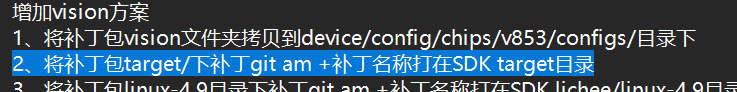
@yanyue MR813的仓库没了吧
newcastle 发布的帖子
-
基于debian发行版的AvaotaOS下的dpkg和apt工具使用方法详解发布在 T Series
在 Linux 系统中,使用源代码进行软件编译能够实现高度定制化的设置,但对于Linux发行版的用户来说,并不是每个人都具备源代码编译的能力。这一点成为了Linux发行商面临的一个软件管理难题,因为这影响了软件在Linux平台上的发行和推广。
为了解决这个问题,Linux发行商开始提供已经编译好并可执行的软件,直接供用户安装使用。不同的Linux发行版采用不同的打包系统,主要分为两大包管理技术阵营:Debian的
.deb和Red Hat的.rpm本文将重点介绍Debian系列发行版中的
dpkg和apt-*工具的详细使用方法。DPKG 简介
dpkg是Debian系统的包管理工具。dpkgis a tool to install, build, remove, and manage Debian packages. 它是Debian的一个底层包管理工具,主要用于对已下载到本地和已安装的软件包进行管理。该机制最早由 Debian Linux 社区开发。通过
dpkg的机制,Debian提供的软件能够轻松安装,并提供安装后的软件信息。许多派生于 Debian 的 Linux 发行版(如B2D、Ubuntu等)大多使用dpkg这个机制来管理软件。deb软件包命名规则
格式为:
Package_Version-Build_Architecture.deb例如:
nano_1.3.10-2_aarch64.deb软件包名称(Package Name):
nano版本(Version Number):1.3.10修订号(Build Number):2平台(Architecture):aarch64dpkg软件包相关文件介绍/etc/dpkg/dpkg.cfg:dpkg包管理软件的配置文件【Configuration file with default options】/var/log/dpkg.log:dpkg包管理软件的日志文件【Default log file (see /etc/dpkg/dpkg.cfg(5) and option --log)】/var/lib/dpkg/available:存放系统所有安装过的软件包信息【List of available packages】/var/lib/dpkg/status:存放系统现在所有安装软件的状态信息/var/lib/dpkg/info:记录安装软件包控制目录的控制信息文件
dpkg数据库dpkg使用文本文件作为数据库来维护系统中软件,包括文件清单、依赖关系、软件状态等详细内容,通常存储在/var/lib/dpkg目录下。通常在status文件中存储软件状态和控制信息。在info/目录下备份控制文件,并在其下的.list文件中记录安装文件清单,其下的.mdasums保存文件的MD5编码。可以用下列命令查询
dpkg数据库dpkg -idpkg子命令为了方便用户使用,
dpkg不仅提供了大量的参数选项, 同时也提供了许多子命令。dpkg-deb:- 功能:
dpkg-deb是一个用于打包和解包Debian软件包(.deb文件)的工具。 - 用法:
- 打包:
dpkg-deb -b <目录> <输出.deb文件> - 解包:
dpkg-deb -x <deb文件> <目标目录>
- 打包:
- 功能:
dpkg-divert:- 功能:
dpkg-divert用于管理Debian软件包中文件的重定向或重命名。 - 用法:
dpkg-divert [选项] [源文件]
- 功能:
dpkg-query:- 功能:
dpkg-query允许用户查询Debian软件包的信息,如已安装软件包的状态、软件包的文件列表等。 - 用法:
- 查询已安装软件包的信息:
dpkg-query -l <软件包名> - 查询软件包的文件列表:
dpkg-query -L <软件包名>
- 查询已安装软件包的信息:
- 功能:
dpkg-split:- 功能:
dpkg-split用于将大型软件包(.deb文件)拆分成较小的部分,以便于分发或存储。 - 用法:
dpkg-split [选项] [输入.deb文件]
- 功能:
dpkg-statoverride:- 功能:
dpkg-statoverride用于修改Debian软件包中文件的权限和属性,以覆盖默认的文件权限设置。 - 用法:
dpkg-statoverride [选项]
- 功能:
start-stop-daemon:- 功能:
start-stop-daemon是一个通用的守护进程管理器,用于启动、停止、重启系统服务。 - 用法:
- 启动服务:
start-stop-daemon --start --name <服务名> - 停止服务:
start-stop-daemon --stop --name <服务名> - 重启服务:
start-stop-daemon --restart --name <服务名>
- 启动服务:
- 功能:
dpkg使用手册安装:
- 安装软件包:
dpkg -i package-name.deb(--install)必须使用完整的deb软件包名称。(安装软件包可分为解包和配置两个步骤) - 解包:
dpkg --unpack package-name.deb解开软件包到系统目录但不进行配置。若与-R一起使用,则参数可以是一个目录。 - 配置:
dpkg --configure package-name.deb配置软件包。 - 列出deb包的内容:
dpkg -c package-name.deb - 递归处理所有与指定目录中找到的符合模式*.deb的常规文件,并且所有的avail操作(可用)可与-i、-A、--install、--unpack一起使用:
-R, --recursive
移除软件包:
- 移除软件包但保留其配置文件:
dpkg -r package-name(--remove) - 清除软件包的所有文件(包括配置文件):
dpkg -P package-name(--purge)
查询:
-
查看系统中软件包名符合模式pattern的软件包:
dpkg -l package-name-pattern(--list) -
查看package-name对应的软件包安装的文件及目录:
dpkg -L package-name(--listfiles) -
显示包的具体信息:
dpkg -p package-name(--print-avail) -
查看package-name(已安装)对应的软件包信息:
dpkg -s package-name(--status) -
从已经安装的软件包中查找包含filename的软件包名称:
dpkg -S filename-search-pattern(--search
: -
列出系统上安装的与dpkg相关的软件包:
dpkg -l \*dpkg* -
查看dpkg软件包安装到系统中的文件:
dpkg -L dpkg
更多dpkg的使用方法可在命令行中使用
man dpkg来查阅,或直接使用dpkg --help。apt
apt 是一个用于管理 Debian 和 Ubuntu 系统上软件包的高级工具。它解决了在安装软件时可能出现的依赖关系问题。Linux 发行版会将软件包放在特定的服务器中,apt 分析这些软件的依赖关系并记录下来。当用户需要安装软件时,apt 会与本地的软件包数据进行比较,然后从网络端获取所有需要的具有依赖属性的软件。
apt 工作原理
Ubuntu 使用集中式的软件仓库机制,将各式各样的软件包存放在软件仓库中,进行有效地组织和管理。这些软件仓库置于许多镜像服务器中,并保持基本一致。用户通过配置文件
/etc/apt/sources.list列出最合适访问的镜像站点地址。例1:apt-get 的更新过程
- 执行
apt-get update命令。 - 程序分析
/etc/apt/sources.list。 - 自动连网寻找配置文件中对应的 Packages/Sources/Release 列表文件,如果有更新则下载之,存入
/var/lib/apt/lists/目录。 - 使用
apt-get install安装相应的包,下载并安装。
软件源配置文件告知系统可以访问的镜像站点地址,但具体的软件资源并不清楚。因此,需要为这些软件资源建立索引文件。用户可以使用
apt-get update命令刷新软件源,建立更新软件包列表。这个命令会扫描每个软件源服务器,并为该服务器所具有的软件包资源建立索引文件,存放在本地的/var/lib/apt/lists/目录中。使用apt-get执行安装、更新操作时,都将依据这些索引文件向软件源服务器申请资源。因此,在计算机空闲时,经常使用apt-get update命令刷新软件源是一个好的习惯。apt 相关文件
/var/lib/dpkg/available文件包含软件包的描述信息,包括当前系统所使用的 Debian 安装源中的所有软件包,包括已安装和未安装的软件包。/etc/apt/sources.list文件记录了软件源的地址。当执行sudo apt-get install xxx命令时,Ubuntu 会从这些地址下载软件包到本地并执行安装。/var/cache/apt/archives目录存放已经下载的软件包。当使用apt-get install安装软件时,软件包会临时存放在这个路径下。/var/lib/apt/lists目录存放着通过apt-get update命令从/etc/apt/sources.list中下载的软件列表文件。
apt 换源
要更改 apt 软件包管理器的软件源,你可以编辑
/etc/apt/sources.list文件,将其中的软件源地址替换为你想要使用的镜像站点地址。你可以选择一个速度快、稳定可靠的镜像站点,通常你可以在该镜像站点的官方网站上找到相应的地址。- 打开终端,以管理员权限编辑
/etc/apt/sources.list文件。你可以使用命令行编辑器如 nano:
sudo nano /etc/apt/sources.list- 在编辑器中,你会看到类似下面的内容:
deb http://archive.ubuntu.com/ubuntu/ focal main restricted deb http://archive.ubuntu.com/ubuntu/ focal-updates main restricted deb http://archive.ubuntu.com/ubuntu/ focal universe deb http://archive.ubuntu.com/ubuntu/ focal-updates universe ...- 将每一行的地址替换为你选择的镜像站点地址。例如,如果你想要使用清华大学的 Ubuntu 镜像,你可以将地址修改为:
deb https://mirrors.tuna.tsinghua.edu.cn/ubuntu/ focal main restricted deb https://mirrors.tuna.tsinghua.edu.cn/ubuntu/ focal-updates main restricted deb https://mirrors.tuna.tsinghua.edu.cn/ubuntu/ focal universe deb https://mirrors.tuna.tsinghua.edu.cn/ubuntu/ focal-updates universe ...- 保存文件并退出编辑器。在 nano 中,按下
Ctrl + O保存,然后按下Ctrl + X退出。 - 最后,运行以下命令以刷新软件包列表并使更改生效:
sudo apt-get update现在,你的系统将会从新的镜像站点下载软件包。
apt 使用方法
apt 是一个功能强大的软件包管理工具,用于在 Debian 和 Ubuntu 等 Linux 发行版上安装、升级和删除软件包。以下是一些常用的 apt 命令和选项:
安装软件包
sudo apt-get install package_name此命令将安装指定的软件包及其所有依赖项。
升级软件包
sudo apt-get upgrade此命令将升级系统中所有已安装软件包的版本。
sudo apt-get dist-upgrade此命令将升级系统中所有软件包的版本,并处理依赖关系的变化。
删除软件包
sudo apt-get remove package_name此命令将从系统中删除指定的软件包,但保留其配置文件。
sudo apt-get purge package_name此命令将从系统中完全删除指定的软件包,包括其配置文件。
搜索软件包
apt-cache search search_term此命令将搜索软件包的名称和描述中包含指定关键字的所有软件包。
显示软件包信息
apt-cache show package_name此命令将显示指定软件包的详细信息,包括版本、描述、依赖关系等。
更新软件包列表
sudo apt-get update此命令将从软件源中下载最新的软件包列表,但不安装或升级软件包。
清理无用软件包
sudo apt-get autoremove此命令将删除系统中无用的软件包,即已经不再被其他软件包依赖的软件包。
这些是一些常用的 apt 命令,你可以通过在终端中运行
man apt-get命令查看 apt 命令的完整手册页。apt-get 和 apt 的区别
Ubuntu 16.04 发布时,一个引人注目的新特性便是 apt 命令的引入。其实早在 2014 年,apt 命令就已经发布了第一个稳定版,只是直到 2016 年的 Ubuntu 16.04 系统发布时才开始引人关注。
随着
apt install package命令的使用频率和普遍性逐步超过apt-get install package,越来越多的其它 Linux 发行版也开始遵循 Ubuntu 的脚步,开始鼓励用户使用 apt 而不是 apt-get。那么,apt-get 与 apt 命令之间到底有什么区别呢?如果它们有类似的命令结构,为什么还需要新的 apt 命令呢?是否 apt 真的比 apt-get 更好?普通用户应该使用新的 apt 命令还是坚持旧有习惯继续使用 apt-get 呢?
好的,让我来对比一下
apt和apt-get命令的区别:- 语法简洁性 :
apt命令通常比apt-get更简洁,因为它整合了apt-get和apt-cache命令的功能,使得常见操作更直观和易用。
- 命令组合 :
apt命令相比apt-get更加综合,可以执行更多的任务而不需要切换到其他命令,因为它合并了apt-get和apt-cache的功能。
- 自动处理依赖关系 :
apt命令在安装和删除软件包时会自动处理依赖关系,使得操作更加方便,而apt-get则需要手动使用apt-get install -f来修复依赖关系。
- 交互性 :
- 一般来说,
apt命令的输出更具有可读性和交互性,它会提供更多的信息和提示,使得用户更容易理解正在发生的操作。
- 一般来说,
- 历史记录 :
apt命令会记录执行过的操作,可以通过apt history命令查看,而apt-get没有类似的功能。
- 更新策略 :
apt命令默认使用更安全的更新策略,即在执行apt upgrade时会避免升级可能导致依赖关系问题的软件包,而apt-get upgrade则没有这种策略。
总的来说,
apt命令提供了更简洁、更易用的方式来管理软件包,尤其适合普通用户使用。而apt-get则在某些特定情况下仍然有其用处,比如在脚本中使用时,或者需要更精细控制的情况下。自建 deb 软件源
获取软件包
软件包的获取来源根据需求选择:
- 自己构建的 deb 软件包
- 从其他存储获取的 deb 软件包
- 从软件源获取目标软件包,如果不知道有哪些依赖包,可以在能上网的机器上执行
apt-get install ***安装一次软件,默认安装包会存储在/var/cache/apt/archives。将获取的软件归置在一个目录中,例如 :/var/packages。如果不需要安装可以使用sudo apt-get -d install <包名>只下载不安装
构建本地 apt 源
生成索引文件
apt-ftparchive packages . > Packages
apt-ftparchive release . > Release
生成签名
以下操作在
/opt/debs目录下进行生成私钥信息
$ gpg --gen-key过程需要填写用户名和邮箱信息提示,以及配置密码信息提示。随后会生成秘钥
添加私钥
gpg -a --export B394614D9EE5DB4DBC84B26FA035D65B714C3CED | apt-key add -
OK
认证
gpg --clearsign -o InRelease Release
gpg -abs -o Release.gpg Release
配置 sources.list 文件
deb file:///opt/debs/ /构建 http 源
使用 nginx / httpd 或其他 web 服务器,将网站的根路径指定为软件源的根路径

-
make menuconfig修改后无法保存发布在 MR Series
各位大佬,请教一下D1s的tina linux,执行make menuconfig,修改以后保存之后。再次进入make menuconfig,发现之前修改的没有保存。怎么回事?
-
回复: 调用ALSA音频采集无法识别库问题发布在 飞凌嵌入式专区
LIBS += -L/root/workspace/allwinner/A40i/bsp/lichee/out/sun8iw11p1/linux/common/buildroot/host/usr/arm-buildroot-linux-gnueabihf/sysroot/usr/lib/ -lasound在pro文件种添加这句好使了

-
调用ALSA音频采集无法识别库问题发布在 飞凌嵌入式专区
我的开发环境是全志A40i,用的配套的底板和核心板,按照手册录音放音没有问题。
之后我想实现的功能是读取录音的数据,并将其转换为指定格式文件输出,同时将数据显示在屏幕上,以波形图的形式,就像录音实时跟踪那种效果
在已经搭建好源码和交叉编译环境下,我编译一个文件在终端提示找不到#include <alsa/asoundlib.h>文件,是因为这句话没有识别,但是系统实际是已经安装了ALSA库的我的源码如下
#define ALSA_PCM_NEW_HW_PARAMS_API #include <stdio.h> #include <stdlib.h> #include <string.h> #include <fcntl.h> #include <sys/ioctl.h> #include <sys/stat.h> #include <sys/types.h> #include <unistd.h> #include <alsa/asoundlib.h> int main() { long loops; int rc; int size; unsigned int val; int dir; char *buffer; snd_pcm_t *handle; snd_pcm_hw_params_t *params; snd_pcm_uframes_t frames; /*以录制模式打开*/ /* Open PCM device for recording (capture). */ rc = snd_pcm_open( &handle, "default", SND_PCM_STREAM_CAPTURE, 0); if (rc < 0) { fprintf(stderr, "unable to open pcm device"); exit(EXIT_FAILURE); } /*分配一个参数对象*/ /* Allocate a hardware parameters object. */ snd_pcm_hw_params_alloca(¶ms); /*初始化参数对象*/ /* Fill it in with default values. */ rc = snd_pcm_hw_params_any(handle, params); if (rc < 0) { printf("Err\n"); } /* Set the desired hardware parameters. */ /*交错模式*/ /* Interleaved mode */ rc = snd_pcm_hw_params_set_access(handle, params, SND_PCM_ACCESS_RW_INTERLEAVED); if (rc < 0) { printf("Err\n"); } /*PCM格式*/ /* Signed 16-bit little-endian format */ rc = snd_pcm_hw_params_set_format(handle, params, SND_PCM_FORMAT_S16_LE); if (rc < 0) { printf("Err\n"); } /*设置通道数*/ /* Two channels (stereo) */ rc = snd_pcm_hw_params_set_channels(handle, params, 2); if (rc < 0) { printf("Err\n"); } /*设置采样率*/ /* 44100 bits/second sampling rate (CD quality) */ val = 44100; rc = snd_pcm_hw_params_set_rate_near(handle, params, &val, &dir); if (rc < 0) { printf("Err\n"); } /*没周期的帧数*/ /* Set period size to 32 frames. */ frames = 32; rc = snd_pcm_hw_params_set_period_size_near(handle, params, &frames, &dir); if (rc < 0) { printf("Err\n"); } /* Write the parameters to the driver */ rc = snd_pcm_hw_params(handle, params); if (rc < 0) { fprintf(stderr, "unable to set hw parameters: %s/n", snd_strerror(rc)); exit(1); } /* Use a buffer large enough to hold one period */ rc = snd_pcm_hw_params_get_period_size(params, &frames, &dir); if (rc < 0) { printf("Err\n"); } size = frames * 4; /* 2 bytes/sample, 2 channels */ buffer = (char *) malloc(size); /* We want to loop for 5 seconds */ rc = snd_pcm_hw_params_get_period_time(params, &val, &dir); loops = 5000000 / val; while (loops > 0) { loops--; rc = snd_pcm_readi(handle, buffer, frames); if (rc == -EPIPE) { /* EPIPE means overrun */ fprintf(stderr, "overrun occurred/n"); //把PCM流置于PREPARED状态,这样下次我们向该PCM流中数据时,它就能重新开始处理数据。 snd_pcm_prepare(handle); } else if (rc < 0) { fprintf(stderr, "error from read: %s/n", snd_strerror(rc)); } else if (rc != (int)frames) { fprintf(stderr, "short read, read %d frames/n", rc); } rc = write(1, buffer, size); if (rc != size) fprintf(stderr, "short write: wrote %d bytes/n", rc); } //调用snd_pcm_drain把所有挂起没有传输完的声音样本传输完全 rc = snd_pcm_drain(handle); //关闭该音频流,释放之前动态分配的缓冲区,退出 rc = snd_pcm_close(handle); free(buffer); return 0; }测试文件引用代码如下
#include <stdio.h>
#include <stdlib.h>
#include <string.h>
#include <fcntl.h>
#include <sys/ioctl.h>
#include <sys/stat.h>
#include <sys/types.h>
#include <unistd.h>
测试程序说明都没有执行,只是单纯的引用alsa库,都无法编译通过
-
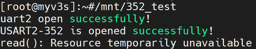
V3s串口连接传感器,读取传感器数据时候出错发布在 V Series
大佬们,我用v3s串口连接传感器,读取传感器数据时候出错,read(): Resource temporarily unavailable,网上说加select,我加了没用,怎么回事啊
#include <stdio.h>
#include <sys/types.h>
#include <sys/stat.h>
#include <fcntl.h>
#include <string.h>
#include <sys/select.h>
#include <termios.h>
#include <stdlib.h>
#include <unistd.h>
#include <stdbool.h>
#include <errno.h>

#define SENSOR "/dev/ttyS2"

int main()
{
	int fd,ret;
	struct	termios option;
	char	cRest[]={0xFE, 0x01, 0x0d, 0x8A, 0x80, 0x0d};
	char	cPower_On[]={0xFE, 0x01, 0x0d, 0x0A, 0x00, 0x0d};
	char	cTem[10];
	fd_set rset;
	struct timeval timeout;
	int rv;

	fd = open(SENSOR,O_RDWR | O_NONBLOCK);
	if(fd < 0)
	{
		perror("open()");
		return -1;
	}
	if(fd > 0)
	{
		printf("uart2 open successfully!\n");
	}

	/*配置串口*/
	memset(&option, 0, sizeof option);
    option.c_iflag = IGNPAR;
	option.c_cflag = B460800 | HUPCL | CS8 | CREAD | CLOCAL;
	option.c_cc[VTIME] = 0;
	option.c_cc[VMIN] = 10;

	ret = tcsetattr(fd, TCSANOW, &option);
	if (ret < 0)
	{
		printf("set USART2-352 failed\n");
		return -1;
	}
	printf("USART2-352 is opened successfully! \n");

	/*配置传感器*/
	write(fd,cRest,6);
	sleep(1);
	write(fd,cPower_On,6);
    while(1)
    {
//		FD_ZERO(&rset);
//		FD_SET(fd,&rset);
//
//		timeout.tv_sec = 5;
//      timeout.tv_usec = 0;
		memset(cTem, 0, 10);

//		rv = select(fd+1,&rset,NULL,NULL,&timeout);
//		if(rv < 0){
//			perror("select error");
//			continue;
//			}
//		else if(rv == 0){
//			perror("select timeout");
//			continue;
//			}
//		else
//		{
			ret=read(fd,cTem,10);
			if(ret < 0)
			{
				perror("read()");
				close(fd);
				break;
			}
			if(ret > 0)
			{
				printf("read data : %s\n",cTem);
			}
		//}
    }

	close(fd);
	return 0;
}
这是程序,编译没问题,运行成这样
-
[SND_ERR][xrun:931]Underrun occure!!! xrun_cnt=1 这是什么意思,偶尔会碰到。欠压吗发布在 A Series
[SND_ERR][xrun:931]Underrun occure!!! xrun_cnt=1
这是什么意思,偶尔会碰到。欠压吗
-
如何将R128的lspsram频率提高至200M?发布在 A Series
使用的FreeRTOS,默认SDK中lspsram运行的频率为192M,如果将频率提高至200M的话,会让lspsram的带宽有稍微的提高,请教一下各位大神有没有对应的教程
-
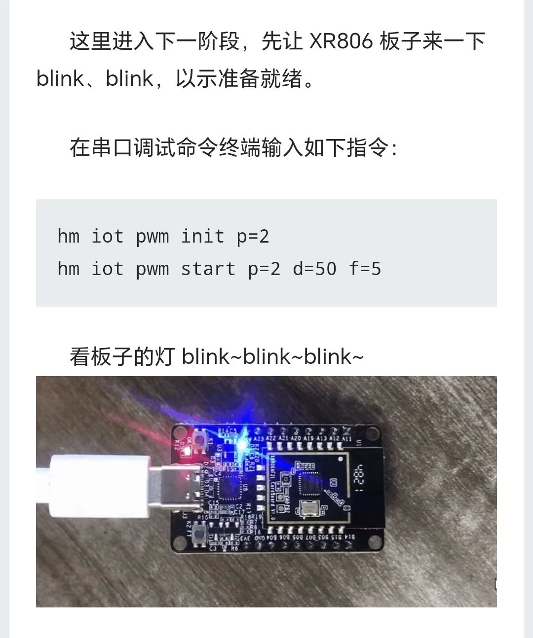
XR806是不是可以直接用命令行和脚本进行编程,不需要再次烧录了呢发布在 Wireless & Analog Series
这个板子上面既然运行了操作系统,那么是不是可以直接用命令行和脚本进行编程,不需要再次烧录了呢?
就像这样
-
h616 怎么加BGA96的DDR4,现在的兼容器件有哪些,软件要怎么适配?发布在 H/F/TV Series
h616 怎么加BGA96的DDR4,现在的兼容器件有哪些?
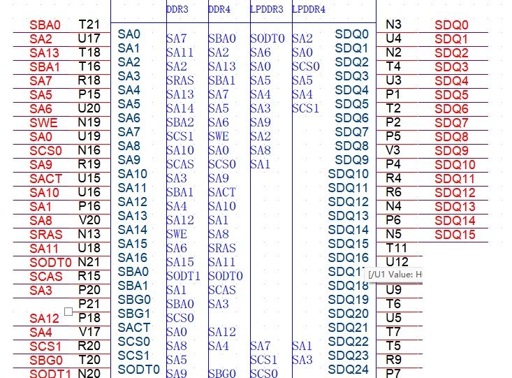
按照这个可以设计原理
这个的兼容器件有哪些?现在看到的板子多为DDR3 的。
SUPPER LIST 中只有一颗是测试过的:H5AN4G6NBJR
现在有更新吗?使用DDR4 X 16 软件上要做哪些修改?
-
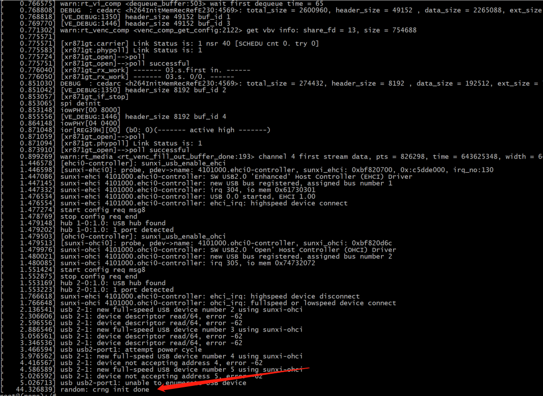
启动阶段应用自启动时从/dev/random设备中获取随机数阻塞时间长发布在 V Series
使用的V851S,内核启动40多秒之后random才初始化完成,如果应用需要从/dev/random设备中获取随机数,需要阻塞几十秒的时间才能成功获取到随机数。
-
如何确认是什么中断唤醒的芯片发布在 Wireless & Analog Series
XR806休眠时频繁被中断唤醒,但没办法定位到是什么中断导致的
被唤醒时,有以下log:
[2022-10-28-18:38:33.456]$ PMA: appos enter mode: standby
[2022-10-28-18:38:33.457]suspend devices took 1 ms
[2022-10-28-18:38:33.458]nvic[1]:8, mask:fff en:0
[2022-10-28-18:38:33.458]wakeup devices pending
[2022-10-28-18:38:33.459]resume devices took 2 ms
[2022-10-28-18:38:33.618]suspend devices took 3 ms
-
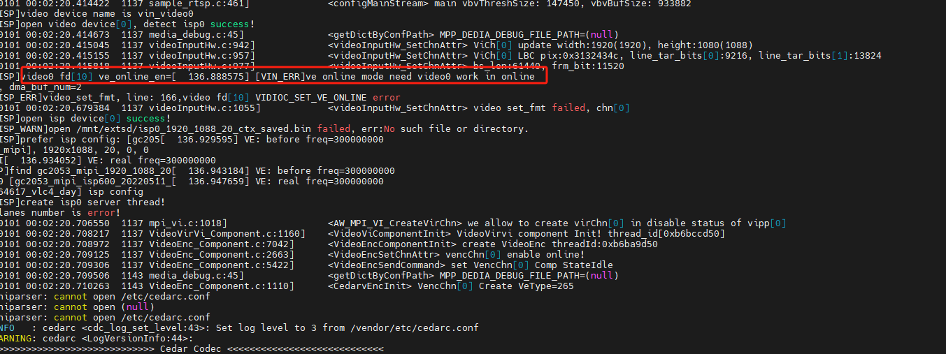
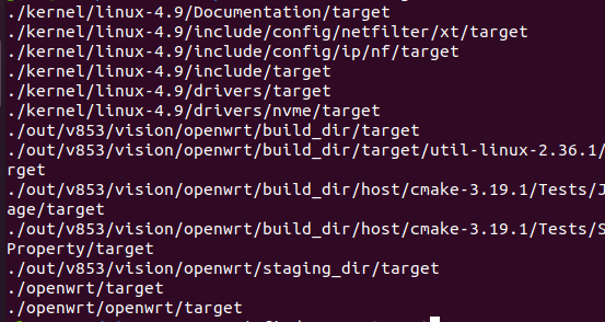
用mpp:sample_virvi2vo测试时出现的ISP文件,GC2053从何而来发布在 V Series
[ 430.271905] [DISP] disp_device_attached_and_enable,line:234:
[ 430.278140] attached ok, mgr0<–>dev0
[ 430.282524] [DISP] disp_device_attached_and_enable,line:247:
[ 430.288732] type:1,mode:0,fmt:rgb,bits:8bits,eotf:4,cs:0 dvi_hdmi:2, range:2 scan:0 ratio:8
I0101 02:55:56.266032 1140 sample_virvi2vo.c:385] Vipp dev[0] vir_chn[0]
[ISP]video device name is vin_video0
[ISP]open video device[0], detect isp0 success!
I0101 02:55:56.266471 1140 media_debug.c:45] MPP_DEDIA_DEBUG_FILE_PATH=(null)
I0101 02:55:56.267184 1140 videoInputHw.c:942] <videoInputHw_SetChnAttr> ViCh[0] update width:360(368), height:640(640)
[ISP]video0 fd[11] ve_online_en=[ 430.572375] [VIN]ve_online close
0, dma_buf_num=0
[ISP]open isp device[0] success!
[ISP]get isp_ctx from /mnt/extsd/isp0_1280_720_60_ctx_saved.bin success!!!
[ISP]prefer isp config: [ov9716_mipi], 1280x720, 60, 0, 0
[ISP_WARN]cannot find ov9716_mipi_1280_720_60_0_0 isp config, use gc2053_mipi_1920_1088_20_0_0 → [gc2053_mip[ 430.604994] [VIN_DEV_I2C_ERR]sensor_write success!,addr:0x36,data:0xDECB1CD2
i_isp600_20220511_164617_vlc4_day]
[ISP]create isp0 server thread!
\tina-v853-open\openwrt\package\allwinner\vision\libAWIspApi\src\isp600\libisp\isp_cfg\isp_ini_parse.c
此文件未被编译, 用mpp:sample_virvi2vo测试时出现的ISP文件,GC2053从何而来
-
T113_pro,如何打包成通用镜像,用PhoenixSuit烧写EMMC发布在 其它全志芯片讨论区
我希望把 buildroot-100ask_t113-pro 工程打包成可以刷emmc的img文件
-
V851s 设备添加了开机logo后提示can't find partition bootloader,并且无法显示开机logo发布在 V Series
V851s 设备添加了开机logo后提示can't find partition bootloader,并且无法显示开机logo,有遇到过类似问题吗
mtdids  : nand0=nand
mtdparts: mtdparts=nand:1024k@0(boot0)ro,3072k@1048576(uboot)ro,1024k@4194304(secure_storage)ro,-(sys)
[01.061]ubi0: attaching mtd4
[01.291]ubi0: scanning is finished
[01.300]ubi0: attached mtd4 (name "sys", size 123 MiB)
[01.305]ubi0: PEB size: 262144 bytes (256 KiB), LEB size: 258048 bytes
[01.311]ubi0: min./max. I/O unit sizes: 4096/4096, sub-page size 2048
[01.317]ubi0: VID header offset: 2048 (aligned 2048), data offset: 4096
[01.324]ubi0: good PEBs: 492, bad PEBs: 0, corrupted PEBs: 0
[01.329]ubi0: user volume: 10, internal volumes: 1, max. volumes count: 128
[01.336]ubi0: max/mean erase counter: 2/1, WL threshold: 4096, image sequence number: 0
[01.343]ubi0: available PEBs: 0, total reserved PEBs: 492, PEBs reserved for bad PEB handling: 20
[01.352]sunxi flash init ok
[01.355]line:724 init_clocks
[01.358]drv_disp_init
request pwm success, pwm7:pwm7:0x2000c00.
[01.372]drv_disp_init finish
[01.606]Loading Environment from SUNXI_FLASH... OK
[01.644]boot_gui_init:start
[01.647][ICN6202 TO LVDS] LINE:0107-->lcd_open_flow:gv029deq open flow!!!! sel:0
[01.654][ICN6202 TO LVDS] LINE:0107-->lcd_open_flow:gv029deq open flow!!!! sel:0
FDT ERROR:fdt_get_all_pin:get property handle pinctrl-0 error:FDT_ERR_INTERNAL
disp_sys_pin_set_state, fdt_set_all_pin, ret=-1
[02.334]boot_gui_init:finish
[02.343][ICN6202 TO LVDS] LINE:0107-->lcd_open_flow:gv029deq open flow!!!! sel:0
[02.594][ICN6202 TO LVDS] LINE:0271-->lcd_panel_init:gv029deq init!!!!
close threshold:4000
crc16_check OK!
get num:0, battery voltage: 0
[06.125][ICN6202 TO LVDS] LINE:0107-->lcd_open_flow:gv029deq open flow!!!! sel:0
partno erro : can't find partition bootloader
** Unable to read file bootlogo.bmp **
[06.146]sunxi bmp info error : unable to open logo file bootlogo.bmp
[06.157]Item0 (Map) magic is bad
[06.160]out of usb burn from boot: not need burn key
damaged volume, update marker is set[06.168]update bootcmd
[06.182][ICN6202 TO LVDS] LINE:0107-->lcd_open_flow:gv029deq open flow!!!! sel:0
[06.190][ICN6202 TO LVDS] LINE:0107-->lcd_open_flow:gv029deq open flow!!!! sel:0
[06.197][ICN6202 TO LVDS] LINE:0107-->lcd_open_flow:gv029deq open flow!!!! sel:0
[06.204]LCD open finish
[06.248]change working_fdt 0x41e8de70 to 0x41e6de70
[06.260]## error: update_fdt_dram_para : FDT_ERR_NOTFOUND
[06.269]update dts
-
SUNXI相关配置文件不存在,如何补齐?发布在 V Series
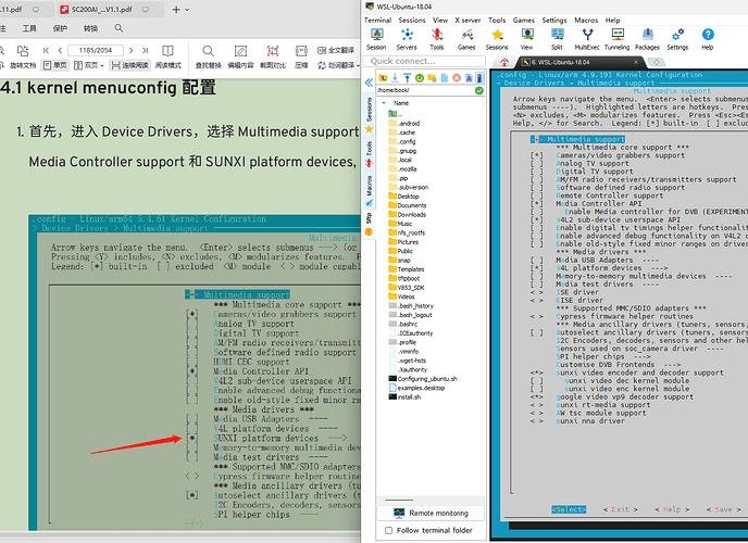
book@100ask:~/V853_SDK/tina-v853-open$ make kernel_menuconfig/
===There is tina environment.===
Note: make is the shell functon in envsetup.sh.

== action: openwrt_build, action_args: kernel_menuconfig/ ==
========ACTION List: build_linuxdev kernel_menuconfig/;========
options :
INFO: ----------------------------------------
INFO: build linuxdev …
INFO: chip: sun8iw21p1
INFO: platform: linux
INFO: kernel: linux-4.9
INFO: board: vision
INFO: output: /home/book/V853_SDK/tina-v853-open/out/v853/vision/openwrt
INFO: ----------------------------------------
INFO: don’t build dtbo …
INFO: build arisc
INFO: build_bootloader: brandy_path= /home/book/V853_SDK/tina-v853-open/brandy/brandy-2.0
INFO: skip build brandy.
INFO: build kernel …
INFO: Prepare toolchain …
Building kernel
/home/book/V853_SDK/tina-v853-open/kernel/linux-4.9/output/lib/modules/4.9.191
CHK include/config/kernel.release
CHK include/generated/uapi/linux/version.h
CHK include/generated/utsrelease.h
CHK scripts/mod/devicetable-offsets.h
CHK include/generated/timeconst.h
CHK include/generated/bounds.h
CHK include/generated/asm-offsets.h
CALL scripts/checksyscalls.sh
CHK include/generated/compile.h
DTC arch/arm/boot/dts/board.dtb
Error: arch/arm/boot/dts/board.dts:220.31-32 syntax error
FATAL ERROR: Unable to parse input tree
scripts/Makefile.lib:313: recipe for target ‘arch/arm/boot/dts/board.dtb’ failed
make[1]: *** [arch/arm/boot/dts/board.dtb] Error 1
arch/arm/Makefile:343: recipe for target ‘dtbs’ failed
make: *** [dtbs] Error 2
make: *** Waiting for unfinished jobs…
ERROR: build kernel_menuconfig/ Failed
INFO: build kernel failed
book@100ask:~/V853_SDK/tina-v853-open$
book@100ask:~/V853_SDK/tina-v853-open$ make kernel_menuconfig/ ===There is tina environment.=== Note: make is the shell functon in envsetup.sh. == action: openwrt_build, action_args: kernel_menuconfig/ == ========ACTION List: build_linuxdev kernel_menuconfig/;======== options : INFO: ---------------------------------------- INFO: build linuxdev … INFO: chip: sun8iw21p1 INFO: platform: linux INFO: kernel: linux-4.9 INFO: board: vision INFO: output: /home/book/V853_SDK/tina-v853-open/out/v853/vision/openwrt INFO: ---------------------------------------- INFO: don’t build dtbo … INFO: build arisc INFO: build_bootloader: brandy_path= /home/book/V853_SDK/tina-v853-open/brandy/brandy-2.0 INFO: skip build brandy. INFO: build kernel … INFO: Prepare toolchain … Building kernel /home/book/V853_SDK/tina-v853-open/kernel/linux-4.9/output/lib/modules/4.9.191 CHK include/config/kernel.release CHK include/generated/uapi/linux/version.h CHK include/generated/utsrelease.h CHK scripts/mod/devicetable-offsets.h CHK include/generated/timeconst.h CHK include/generated/bounds.h CHK include/generated/asm-offsets.h CALL scripts/checksyscalls.sh CHK include/generated/compile.h DTC arch/arm/boot/dts/board.dtb Kernel: arch/arm/boot/Image is ready Building modules, stage 2. MODPOST 27 modules Kernel: arch/arm/boot/zImage is ready Kernel: arch/arm/boot/uImage is ready ‘arch/arm/boot/Image’ → ‘output/bImage’ ‘arch/arm/boot/uImage’ → ‘output/uImage’ ‘arch/arm/boot/zImage’ → ‘output/zImage’ Copy rootfs.cpio.gz for arm Building modules [GPU]: No GPU type is configured in /home/book/V853_SDK/tina-v853-open/kernel/linux-4.9/.config. INFO: build dts … INFO: Prepare toolchain … removed ‘/home/book/V853_SDK/tina-v853-open/out/v853/vision/openwrt/.board.dtb.d.dtc.tmp’ removed ‘/home/book/V853_SDK/tina-v853-open/out/v853/vision/openwrt/.board.dtb.dts.tmp’ ‘/home/book/V853_SDK/tina-v853-open/kernel/linux-4.9/arch/arm/boot/dts/.board.dtb.d.dtc.tmp’ → ‘/home/book/V853_SDK/tina-v853-open/out/v853/vision/openwrt/.board.dtb.d.dtc.tmp’ ‘/home/book/V853_SDK/tina-v853-open/kernel/linux-4.9/arch/arm/boot/dts/.board.dtb.dts.tmp’ → ‘/home/book/V853_SDK/tina-v853-open/out/v853/vision/openwrt/.board.dtb.dts.tmp’ INFO: build rootfs … ==mkcmd.sh: build_openwrt_rootfs kernel_menuconfig/== make: Entering directory ‘/home/book/V853_SDK/tina-v853-open/openwrt/openwrt’ make[1]: Entering directory ‘/home/book/V853_SDK/tina-v853-open/openwrt/openwrt’ CreateSoftLink /home/book/V853_SDK/tina-v853-open/openwrt/openwrt/tmp link to /home/book/V853_SDK/tina-v853-open/out/v853/vision/openwrt/tmp CreateSoftLink /home/book/V853_SDK/tina-v853-open/openwrt/openwrt/staging_dir link to /home/book/V853_SDK/tina-v853-open/out/v853/vision/openwrt/staging_dir make[2]: Entering directory ‘/home/book/V853_SDK/tina-v853-open/openwrt/openwrt’ make[2]: Leaving directory ‘/home/book/V853_SDK/tina-v853-open/openwrt/openwrt’ Check Vendor Package… CreateSoftLink /home/book/V853_SDK/tina-v853-open/openwrt/openwrt/package/subpackage link to /home/book/V853_SDK/tina-v853-open/openwrt/package end WARNING: Makefile ‘package/subpackage/thirdparty/multimedia/gstreamer/gst1-libav/Makefile’ has a build dependency on ‘libgstreamer1’, which does not exist WARNING: Makefile ‘package/subpackage/thirdparty/multimedia/gstreamer/gst1-libav/Makefile’ has a build dependency on ‘gstreamer1-plugins-base’, which does not exist WARNING: Makefile ‘package/subpackage/thirdparty/multimedia/gstreamer/gst1-omx/Makefile’ has a dependency on ‘libgst1gl’, which does not exist WARNING: Makefile ‘package/subpackage/thirdparty/multimedia/gstreamer/gst1-plugins-aw/Makefile’ has a build dependency on ‘libgstreamer1’, which does not exist WARNING: Makefile ‘package/subpackage/thirdparty/multimedia/gstreamer/gst1-plugins-aw/Makefile’ has a build dependency on ‘gstreamer1-plugins-base’, which does not exist WARNING: Makefile ‘package/subpackage/thirdparty/multimedia/gstreamer/gst1-plugins-aw/Makefile’ has a build dependency on ‘gstreamer1-plugins-good’, which does not exist WARNING: Makefile ‘package/subpackage/thirdparty/multimedia/gstreamer/gst1-plugins-bad/Makefile’ has a dependency on ‘wayland’, which does not exist WARNING: Makefile ‘package/subpackage/thirdparty/multimedia/gstreamer/gst1-plugins-bad/Makefile’ has a dependency on ‘wayland-protocols’, which does not exist WARNING: Makefile ‘package/subpackage/thirdparty/multimedia/gstreamer/gst1-plugins-bad/Makefile’ has a dependency on ‘opencv’, which does not exist WARNING: Makefile ‘package/subpackage/thirdparty/multimedia/gstreamer/gst1-plugins-bad/Makefile’ has a dependency on ‘libgst1badvideo’, which does not exist WARNING: Makefile ‘package/subpackage/thirdparty/multimedia/gstreamer/gst1-plugins-bad/Makefile’ has a dependency on ‘libgst1gl’, which does not exist WARNING: Makefile ‘package/subpackage/thirdparty/multimedia/gstreamer/gst1-plugins-bad/Makefile’ has a build dependency on ‘libgstreamer1’, which does not exist WARNING: Makefile ‘package/subpackage/thirdparty/multimedia/gstreamer/gst1-plugins-bad/Makefile’ has a build dependency on ‘gstreamer1-plugins-base’, which does not exist WARNING: Makefile ‘package/subpackage/thirdparty/multimedia/gstreamer/gst1-plugins-base/Makefile’ has a build dependency on ‘libgstreamer1’, which does not exist WARNING: Makefile ‘package/subpackage/thirdparty/multimedia/gstreamer/gst1-plugins-good/Makefile’ has a build dependency on ‘libgstreamer1’, which does not exist WARNING: Makefile ‘package/subpackage/thirdparty/multimedia/gstreamer/gst1-plugins-good/Makefile’ has a build dependency on ‘gstreamer1-plugins-base’, which does not exist WARNING: Makefile ‘package/subpackage/thirdparty/multimedia/gstreamer/gst1-plugins-ugly/Makefile’ has a build dependency on ‘libgstreamer1’, which does not exist WARNING: Makefile ‘package/subpackage/thirdparty/multimedia/gstreamer/gst1-plugins-ugly/Makefile’ has a build dependency on ‘gstreamer1-plugins-base’, which does not exist WARNING: Makefile ‘package/kernel/linux/Makefile’ has a dependency on ‘kmod-sunxi-rf-wlan’, which does not exist WARNING: Makefile ‘package/subpackage/thirdparty/gui/qt/qt5/Makefile’ has a dependency on ‘weston’, which does not exist WARNING: Makefile ‘package/subpackage/thirdparty/gui/qt/qt5/Makefile’ has a dependency on ‘wayland’, which does not exist WARNING: Makefile ‘package/subpackage/thirdparty/gui/qt/qt5/Makefile’ has a dependency on ‘qt5-multimediawidgets’, which does not exist WARNING: Makefile ‘package/subpackage/thirdparty/gui/qt/qt5/Makefile’ has a build dependency on ‘libstdcpp’, which does not exist make[2]: Entering directory ‘/home/book/V853_SDK/tina-v853-open/openwrt/openwrt/scripts/config’ make[2]: ‘conf’ is up to date. make[2]: Leaving directory ‘/home/book/V853_SDK/tina-v853-open/openwrt/openwrt/scripts/config’ copy from /home/book/V853_SDK/tina-v853-open/openwrt/target/v853/v853-vision/defconfig target/linux/generic/image/Config.in:12:warning: choice default symbol ‘uImage’ is not contained in the choice target/linux/generic/image/Config.in:47:warning: choice default symbol ‘uImage’ is not contained in the choice target/linux/generic/image/Config.in:72:warning: choice default symbol ‘CONFIG_BOOT_IMAGE_NAME_SUFFIX_NONE’ is not contained in the choice target/linux/generic/image/Config.in:89:warning: choice default symbol ‘CONFIG_ROOTFS_IMAGE_NAME_SUFFIX_NONE’ is not contained in the choice No change to .config copy to /home/book/V853_SDK/tina-v853-open/openwrt/target/v853/v853-vision/defconfig make[2]: Entering directory ‘/home/book/V853_SDK/tina-v853-open/openwrt/openwrt’ Makefile:29: “NOTE: Will skip kernel build.” The command image-prereq(include/kernel-build.mk) execute. time: target/linux/prereq#0.19#0.09#0.26 make[2]: Leaving directory ‘/home/book/V853_SDK/tina-v853-open/openwrt/openwrt’ make[1]: Leaving directory ‘/home/book/V853_SDK/tina-v853-open/openwrt/openwrt’ make[1] kernel_menuconfig/ make -r kernel_menuconfig/: build failed. Please re-run make with -j1 V=s or V=sc for a higher verbosity level to see what’s going on /home/book/V853_SDK/tina-v853-open/openwrt/openwrt/include/toplevel.mk:236: recipe for target ‘kernel_menuconfig/’ failed make: *** [kernel_menuconfig/] Error 1 make: Leaving directory ‘/home/book/V853_SDK/tina-v853-open/openwrt/openwrt’ INFO: build_openwrt_rootfs failed
-
如何检测mqtt的连接状态?发布在 GUI
qt5+qmqtt库,连上网络后拔掉网线,没有触发disconnect和error信号,isConnectedToHost()返回的也是true。
先拔掉网线再运行程序,就可以触发error()信号,isConnectedToHost()返回也是false。
请教,如何检测mqtt的连接状态?
-
VFS: Cannot open root device "mmcblk0p5" or unknown-block(0,0)发布在 其它全志芯片讨论区
好像是VFS找不到了,有没有大佬帮忙看看什么情况
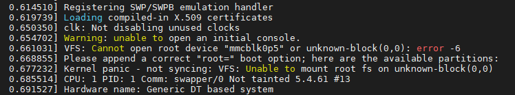
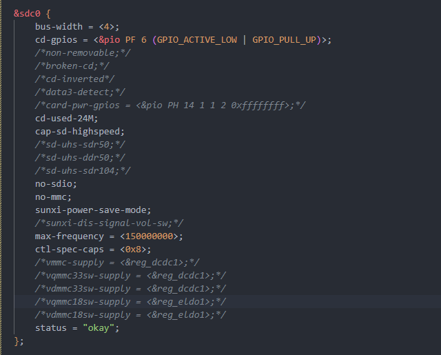
下面是DTS的设置,好像是没找到MMC?
-
f1c100S用tf卡构建系统,tf卡启动失败发布在 其它全志芯片讨论区
使用荔枝派官网的教程用tf卡构建系统,
第一分区:boot.scr zImage suniv-f1c100s-licheepi-nano.dtb
第二分区:rootfs解压的文件,但是插上tf卡启动不了,这是漏了哪一步吗
U-Boot 2018.01-05688-ga9729b3241-dirty (Mar 27 2023 - 03:14:35 -0400) Allwinner Technology

CPU:   Allwinner F Series (SUNIV)
Model: Lichee Pi Nano
DRAM:  32 MiB
MMC:   SUNXI SD/MMC: 0
SF: Detected w25q128bv with page size 256 Bytes, erase size 4 KiB, total 16 MiB
*** Warning - bad CRC, using default environment

Setting up a 800x480 lcd console (overscan 0x0)
In:    serial@1c25000
Out:   serial@1c25000
Err:   serial@1c25000
Net:   No ethernet found.
starting USB...
No controllers found
Hit any key to stop autoboot:  0
SF: Detected w25q128bv with page size 256 Bytes, erase size 4 KiB, total 16 MiB
device 0 offset 0x100000, size 0x4000
SF: 16384 bytes @ 0x100000 Read: OK
device 0 offset 0x110000, size 0x400000
SF: 4194304 bytes @ 0x110000 Read: OK
=>
=>
-
芒果派t113s3板子的tina,ubuntu用哪个版本比较好?22.04似乎不少问题发布在 其它全志芯片讨论区
大佬们,编译 mq-r t113s3 板子的tina,ubuntu用哪个版本?22.04似乎不少问题
-
axp2101 aldo2开关控制问题发布在 其它全志芯片讨论区
1.axp2101的控制aldo2的开关是在board.dts里面设置吗?
2.axp2101每个输出管脚的电压在哪里设置的?也是board.dts吗?
-
裸机环境下电阻触摸屏的校正方式发布在 GUI
本文转载自:https://whycan.com/t_6896.html
电阻触摸屏校正,一般采用5点校正法,核心就是解方程,得系数。具体实现tslib里面就有,但裸机的话,那就的靠自己了,今天抽了点时间,重现实现了之前因框架变化而屏蔽掉的代码,算补全这个功能。
求解方程实现函数
struct tscal_t {
	int x[5], xfb[5];
	int y[5], yfb[5];
	int a[7];
	int index;
};

static int perform_calibration(struct tscal_t * cal)
{
	float n, x, y, x2, y2, xy, z, zx, zy;
	float det, a, b, c, e, f, i;
	float scaling = 65536.0;
	int j;

	n = x = y = x2 = y2 = xy = 0;
	for(j = 0; j < 5; j++)
	{
		n += 1.0;
		x += (float)cal->x[j];
		y += (float)cal->y[j];
		x2 += (float)(cal->x[j]*cal->x[j]);
		y2 += (float)(cal->y[j]*cal->y[j]);
		xy += (float)(cal->x[j]*cal->y[j]);
	}

	det = n * (x2 * y2 - xy * xy) + x * (xy * y - x * y2) + y * (x * xy - y * x2);
	if(det < 0.1 && det > -0.1)
		return 0;

	a = (x2 * y2 - xy * xy) / det;
	b = (xy * y - x * y2) / det;
	c = (x * xy - y * x2) / det;
	e = (n * y2 - y * y) / det;
	f = (x * y - n * xy) / det;
	i = (n * x2 - x * x) / det;

	z = zx = zy = 0;
	for(j = 0; j < 5; j++)
	{
		z += (float)cal->xfb[j];
		zx += (float)(cal->xfb[j] * cal->x[j]);
		zy += (float)(cal->xfb[j] * cal->y[j]);
	}
	cal->a[0] = (int)((b * z + e * zx + f * zy) * (scaling));
	cal->a[1] = (int)((c * z + f * zx + i * zy) * (scaling));
	cal->a[2] = (int)((a * z + b * zx + c * zy) * (scaling));

	z = zx = zy = 0;
	for(j = 0; j < 5; j++)
	{
		z += (float)cal->yfb[j];
		zx += (float)(cal->yfb[j] * cal->x[j]);
		zy += (float)(cal->yfb[j] * cal->y[j]);
	}
	cal->a[3] = (int)((b * z + e * zx + f * zy) * (scaling));
	cal->a[4] = (int)((c * z + f * zx + i * zy) * (scaling));
	cal->a[5] = (int)((a * z + b * zx + c * zy) * (scaling));
	cal->a[6] = (int)scaling;

	return 1;
}
校正参数有7个数,最后一个是scaling,一般是65536
"ts-ns2009@0": {
		"i2c-bus": "i2c-v3s.0",
		"slave-address": 72,
		"median-filter-length": 5,
		"mean-filter-length": 5,
		"calibration": [14052, 21, -2411064, -67, 8461, -1219628, 65536],
		"poll-interval-ms": 10
	},
这里有个特殊的校正参数,设定这个校正参数后,坐标不做任何变化,采样多少,就输出多少,用于获取原始采样值
[1, 0, 0, 0, 1, 0, 1]有了校正参数后,所有坐标通过,如下公式,就可以进行校正坐标了
*x = (filter->cal[2] + filter->cal[0] * tx + filter->cal[1] * ty) / filter->cal[6];
	*y = (filter->cal[5] + filter->cal[3] * tx + filter->cal[4] * ty) / filter->cal[6];
校正程序代码:
https://gitee.com/xboot/xboot/blob/master/src/kernel/command/cmd-tscal.c
-
T507将pwm2 status修改disabled 就造成系统不断重启有可能是什么原因?发布在 其它全志芯片讨论区
如题,我在T507将pwm2 status修改disabled 就造成系统不断重启
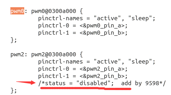
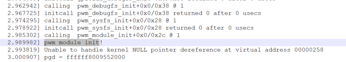
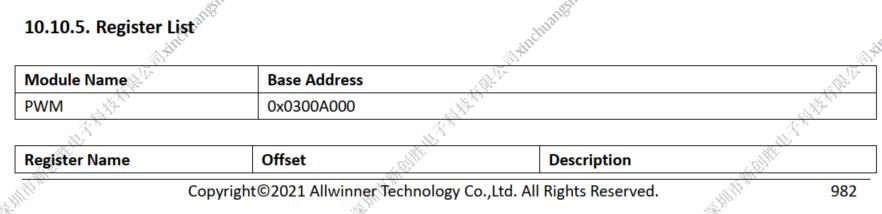
手册上给的pwm2和pwm0的设备树地址是一模一样的,是不是这种情况下不能单独disable 某一个pwm?
-
使用创龙A40i评估板,想做arm与FPGA sdio 通信,请问ARM的设备树配置在哪里呀?发布在 创龙科技专区
使用创龙A40i评估板,想做arm与FPGA sdio 通信,请问ARM的设备树配置在哪里呀?
-
回复: lvgl-desktop 編譯錯誤发布在 其它全志芯片讨论区
解決了,需要 enable buildroot libinput library
#make menuconfig
Target packages → Libraries → Hardware handling → libinput
-
lvgl-desktop 編譯錯誤发布在 其它全志芯片讨论区
使用 buildroot-100ask_t113-pro 在 enable lvgl desktop 之後做 make 會得到錯誤:
Makefile:578: *** libinput is in the dependency chain of lvgl-desktop that has added it to its _DEPENDENCIES variable without selecting it or depending on it from Config.in. Stop.
make: *** [Makefile:84: _all] Error 2
-
几个直接在TigerISP上查看Sensor分辨率的方法发布在 V Series
TigerISP是全志提供的量产工具,在连接TigerISP时需要填写Sensor名称、Sensor分辨率、Sensor帧率及选择ISP通道、Vich、Wdr模式等......
- 准备工作:打开debugfs
操作:adb shell进入系统后输入以下两个命令:
mount -t debugfs mone /sys/kernel/debug
cat /sys/kernel/debug/mpp/vi
1.对于平板产品,可能出现以下情况:
输入命令回车后,只能看到Sensor名称、Vich和ISP,看不到分辨率、帧率等
有两种解决方式:
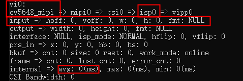
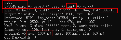
(1)打开摄像机应用,拍摄一张照片,再执行命令cat /sys/kernel/debug/mpp/vi,结果如下图,可以看到,Sensor名称为ov5648_mipi,Vich可以选择0,则对应ISP选择0,分辨率为2592*1944,帧率为1000/avg=10
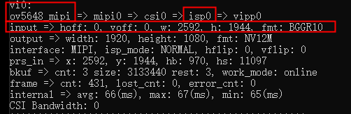
(2)直接打开ISP工具,填入Sensor名称、Vich和ISP,不知道的分辨率和帧率先填写为1920*1080,30fps,点击连接工具,连接成功后,再通过adb shell执行以上两个命令即可看到分辨率等。
关于WDR的选择,WDR的选择要看Sensor的驱动配置,在无法查看的情况下,优先默认选择None,Rear/Front是选择前后摄像头
2.对于行车记录仪等产品,在产品启动后就会开启摄像,会占用摄像头,那么在执行命令前就需要关掉所有占用摄像头的进程,
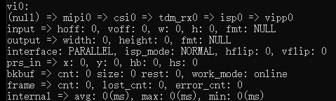
命令如下:adb shell进入系统 killall sdvcam//(执行3次,一般第3次会提示没有进程可以关闭) mount -t debugfs mone /sys/kernel/debug cat /sys/kernel/debug/mpp/vi如果执行命令后看不到任何信息,连Sensor名称都没有,如下图
类似上述方法2,Sensor名称可以填一个已知的名称,例如gc2053_mipi,分辨率填1920*1080, 30fps,其他选择默认,点击连接工具,再通过adb shell执行两个命令即可看到分辨率等。
-
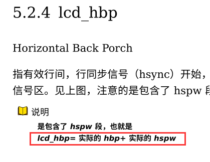
关于全志T113开发板接7寸LCD屏幕显示异常问题的解决方案发布在 其它全志芯片讨论区
在入手全志T113之后,第一时间移植好了之前6ull平台的rootfs。但是在测试QT的过程中发现屏幕最右侧有一部分显示不正常,经过初步推测应该是RGB行场同步时序有问题。本以为在设备树里面稍作修改之后就能OK,但是居然前前后后一共花了至少三个星期的时间。
这里就不给分析经过了,因为是真的真的太漫长了,搞得我头都大了。真的是要吐槽一下全志的代码:
1.函数名字真的看得头疼
2.代码杂乱无章,大量使用全局变量,让分析各种没头绪。
然后在这里直接给出最终分析的结果:
1.设备树里面timing,除了width、height、lcd_x和lcd_y之外的参数全没有用上(一开始不停的源码里面找这些参数在什么地方配置的,最后发现特么的根本就没有地方使用过这些参数)
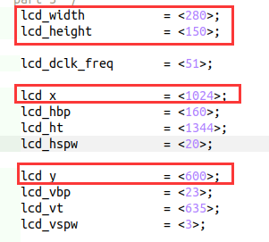
2.width和height主要是用来计算dpi使用的,我这里写的280最终计算出来的dpi大概是97左右,windows标准的是96,反正相差无几我也没有细调了,lcd_x和lcd_y在原来的代码里主要是用来计算内核里面有一张图片的缩放使用的。
3.lcd timing寄存器里面的值是在uboot里面设置好之后在kernel里面直接拿来用的。
4.uboot里面的timing计算方式有问题,应该是百问没有仔细阅读全志文档的原因造成的,这也是使得屏幕显示向左平移了几十个像素的原因
5.我忘记我要说什么了…
接下来就说怎么处理吧:
1.首先按照全志的文档把设备树里面的timing改了
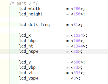
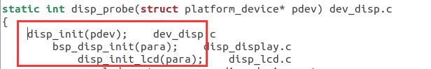
2.打开 drivers/video/fbdev/sunxi/disp2/disp/de/disp_lcd.c 然后找到 s32 disp_init_lcd(struct disp_bsp_init_para* para) 函数,在前面加上一段代码
typedef struct
{
	volatile unsigned int Timing0;
	volatile unsigned int Timing1;
	volatile unsigned int Timing2;
	volatile unsigned int Timing3;
}RegTypeDef;

static void set_lcd_timings(unsigned int dwLcdRegBase, struct disp_video_timings* pTimings)
{
	RegTypeDef* reg;
	unsigned int dwWidth, dwHeight;
	unsigned int dwHT, dwHBP;
	unsigned int dwVT, dwVBP;
	unsigned int dwHSPW, dwVSPW;

	reg = (RegTypeDef*)(dwLcdRegBase + 0x48);

	dwWidth = pTimings->x_res;
	dwHSPW = pTimings->hor_sync_time;
	dwHBP = pTimings->hor_back_porch + pTimings->hor_sync_time;	//在官方文档里:hbp = hbp + hspw,然而在全志的代码里面又将hspw其减去,所以在这里需要加回来
	dwHT = pTimings->hor_total_time;

	dwHeight = pTimings->y_res;;
	dwVSPW = pTimings->ver_sync_time;
	dwVBP = pTimings->ver_back_porch + pTimings->ver_sync_time;
	dwVT = pTimings->ver_total_time;

	reg->Timing0 = ((dwWidth - 1) << 16) | (dwHeight - 1);
	reg->Timing1 = ((dwHT - 1) << 16) | (dwHBP - 1);
	reg->Timing2 = (((dwVT - 1) * 2) << 16) | (dwVBP - 1);
	reg->Timing3 = ((dwHSPW - 1) << 16) | (dwVSPW - 1);

	printk("width: %d, hspw: %d, hbp: %d, ht: %d\n", dwWidth, dwHSPW, dwHBP, dwHT);
	printk("height: %d, vspw: %d, vbp: %d, vt: %d\n", dwHeight, dwVSPW, dwVBP, dwVT);
}
然后在 s32 disp_init_lcd(struct disp_bsp_init_para* para) 函数的 disp_lcd_init(lcd, lcd->disp); 后面加上
set_lcd_timings(para->reg_base[DISP_MOD_LCD0], &lcd->timings);3.最后编译烧写进去之后重启就搞定了…
4.uboot我就懒得修改了,凑合用吧
-
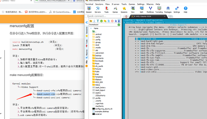
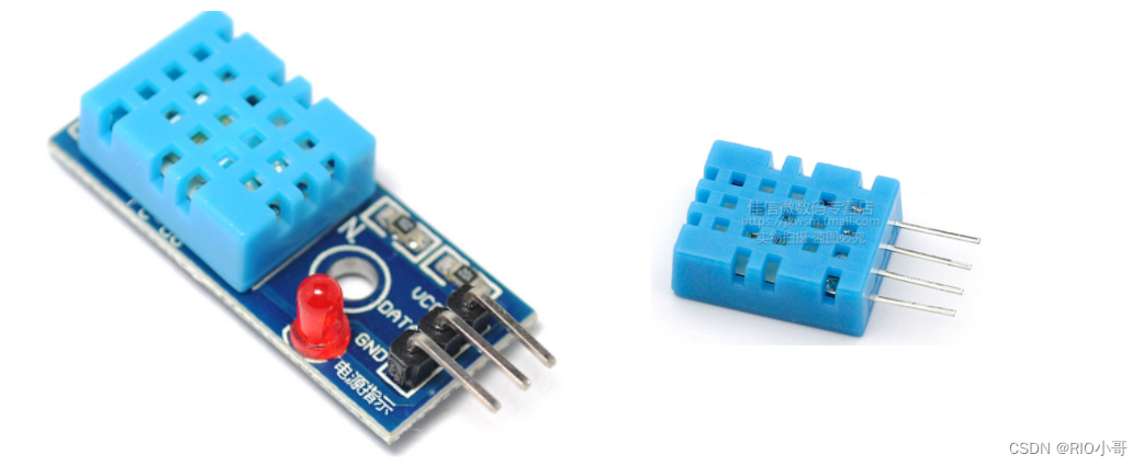
香橙派(全志H616)+ DHT11温湿度传感器的驱动教程发布在 H/F/TV Series
一、前言
最近写DHT11的代码到香橙派(全志H616)上,发现网上案例基本上都是树莓派+DHT11的居多,香橙派的少,少数找得到的代码跑起来也是不稳定或者数据相对不太准确,于是这里自己写了一篇,供大家参考和批评指正
产品概述
DHT11数字温湿度传感器是一款含有已校准数字信号输出的温湿度复合传感器,应用领域:暖通 空调;汽车;消费品;气象站;湿度调节器;除湿器;家电;医疗;自动控制
特点
- 相对湿度和温度测量
- 全部校准,数字输出
- 长期稳定性
- 超长的信号传输距离:20米
- 超低能耗:休眠
- 4 引脚安装:可以买封装好的
- 完全互换 : 直接出结果,不用转化
数据传送逻辑
只有一根数据线DATA,主控MCU发送序列指令给DHT11模块,模块一次完整的数据传输为40bit,高位先出数据格式
8bit湿度整数数据+8bit湿度小数数据+8bi温度整数数据+8bit温度小数数据+8bit校验和关于校验
假设接收到的40位数据为:
计算:0011 0101 + 0000 0000 + 0001 1000 + 0000 0100 = 0101 0001(校验位)
DHT11通信时序
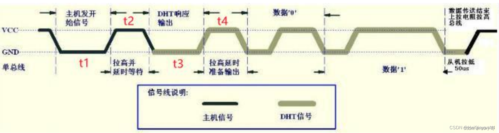
(1)主机发送起始信号
首先单片机将连接DHT11 DATA引脚的GPIO口输出低电平,且低电平保持时间不能小于18ms (t1)最大不能超多30ms,然后拉高数据线20~40us (t2) ,等待读取DHT11的响应信号。(2)检测从机应答信号
DHT11的DATA引脚检测到外部信号有低电平(t1),并等待外部低电平信号结束(t2),延迟后DHT11的DATA引脚处于输出状态,之后DHT11开始输出80 us (t3)的低电平作为应答信号,紧接着输出80us(t4)的高电平通知主机准备接收数据。
主机的I/O此时处于输入状态,检测I/O有低电平(DHT11应答信号)后,等待80us的高电平后接受数据。(3)数据传输
由DHT11的DATA引脚输出40位数据,采用高位优先方式(MSB),微处理器根据I/0电平的变化接收40位数据。
位数据“0”的格式为:50微秒的低电平和26-28us的高电平。
位数据“1”的格式为:50微秒的低电平加70us的高电平。二、代码
主体代码主要是利用多线程,用户每发送一次数据读取请求,创建一个线程用于读取数据;利于提高代码的健壮性和扩展性;
同时引入一个blockFlag的标志位,避免子线程代码跑飞无法退出的问题;
并且在测试过程中发现有偶尔测试出温度明显错误的数据;考虑到可能是由于环境、传感器、延时误差等原因导致的数据不准确问题,所以程序中会将超过50°C的数据视为无效数据,自行重新测试,最多自行重试5次
GPIO初始化
因为发送给DHT11的起始信号是先拉低电平,所以拉低电平前先维持一个稳定的高电平状态
void GPIO_init(int gpio_pin)
{
    pinMode(gpio_pin, OUTPUT); // set mode to output
    digitalWrite(gpio_pin, 1); // output a high level
    delay(1000);
}
起始信号
因为DHT11的触发是单次的,即每发送一次起始信号,才会检查一次温湿度,所以发送起始信号的代码必然是要多次复用,所以这里也封装成一个函数
void DHT11_Start_Sig()
{
	pinMode(pinNumber,OUTPUT);	//让GPIO为输出模式
	digitalWrite(pinNumber,HIGH);
	digitalWrite(pinNumber,LOW);
	delay(25);	//维持25ms的低电平
	digitalWrite(pinNumber,HIGH);	//转化为高电平,等待DHT11的响应信号

	pinMode(pinNumber,INPUT);
	//响应信号为80us电平与80us的准备信号

	pullUpDnControl(pinNumber,PUD_UP);	//进行上拉,增加稳定性,非必选
	delayMicroseconds(35);	//维持35微秒
}
读取数据
void* readSensorData(void *arg)
{
    uint8 crc;
    uint8 i;
	int attempt = 5;	//调用一次最多尝试测5次

	while(attempt)
	{
		databuf = 0;	//清空数据存储buf
		crc = 0;		//清空校验位数据存储buf
		DHT11_Start_Sig();

	    if(digitalRead(pinNumber)==0) //检测DHT11是否应答,应答则继续下一步
	    {
	      while(!digitalRead(pinNumber)); //wait to high

          //读取4个数据,合计32位
	      for(i=0;i<32;i++)
	      {
		       while(digitalRead(pinNumber)); //data clock start
		       while(!digitalRead(pinNumber)); //data start
	           delayMicroseconds(HIGH_TIME);	//如果32微秒后,仍然检测到是高电平,则该数据位为1
	           databuf*=2;		//移位到buf的更高位
	           if(digitalRead(pinNumber)==1) //1
	            {
	                databuf++;
	            }
	      }
          //读取校验位
	      for(i=0;i<8;i++)
	      {
			  	while(digitalRead(pinNumber)); //data clock start
			    while(!digitalRead(pinNumber)); //data start
		        delayMicroseconds(HIGH_TIME);
		        crc*=2;
		        if(digitalRead(pinNumber)==1) //1
		        {
		           crc++;
		        }
	      }

		  //用于校验数据的准确性,当温度大于50时,视为无效数据
	  	  if(((databuf>>8)&0xff) > 50)
		  {
			 attempt--;
			 delay(500);	//不加这段延迟,下一次传感器来不及响应
			 continue;
		  }
		  else
		  {
            //打印数据
		  	printf("Congratulations ! Sensor data read ok!\n");
	       	printf("RH:%lu.%lu\n",(databuf>>24)&0xff,(databuf>>16)&0xff);
	       	printf("TMP:%lu.%lu\n",(databuf>>8)&0xff,databuf&0xff);
			blockFlag = 0;	//用来避免程序有时候跑飞,卡在此函数中,无法跳出
			return (void*)1;
		  }
	   }
	   else		//dht not answer
	   {
	   		blockFlag = 0;
	   		printf("Sorry! Sensor dosent ans!\n");
	        return (void*)0;
	   }
	}

    //如果代码执行到这里,则证明尝试读取了5次数据,都是不准确的数据
	blockFlag = 0;
	printf("get data fail\n");
	return (void*)2;
}
整体代码
#include <wiringPi.h>
#include <stdio.h>
#include <stdlib.h>
#include <string.h>
#include <pthread.h>
#include "contrlDevices.h"

typedef unsigned char uint8;
typedef unsigned int  uint16;
typedef unsigned long uint32;

#define HIGH_TIME 32

int pinNumber = 6;  //use gpio1 to read data
uint32 databuf;
int blockFlag;


void GPIO_init(int gpio_pin)
{
    pinMode(gpio_pin, OUTPUT); // set mode to output
    digitalWrite(gpio_pin, 1); // output a high level
    delay(1000);
    //return;
}


void DHT11_Start_Sig()
{
	pinMode(pinNumber,OUTPUT);
	digitalWrite(pinNumber,HIGH);
	digitalWrite(pinNumber,LOW);
	delay(25);
	digitalWrite(pinNumber,HIGH);

	pinMode(pinNumber,INPUT);
	//响应信号为80us电平与80us的准备信号

	pullUpDnControl(pinNumber,PUD_UP);
	delayMicroseconds(35);
}


void* readSensorData(void *arg)
{
    uint8 crc;
    uint8 i;
	int attempt = 5;	//调用一次最多尝试测5次

	while(attempt)
	{
		databuf = 0;	//清空数据存储buf
		crc = 0;		//清空校验位数据存储buf
		DHT11_Start_Sig();

	    if(digitalRead(pinNumber)==0) //检测DHT11是否应答,应答则继续下一步
	    {
	      while(!digitalRead(pinNumber)); //wait to high

          //读取4个数据,合计32位
	      for(i=0;i<32;i++)
	      {
		       while(digitalRead(pinNumber)); //data clock start
		       while(!digitalRead(pinNumber)); //data start
	           delayMicroseconds(HIGH_TIME);	//如果32微秒后,仍然检测到是高电平,则该数据位为1
	           databuf*=2;		//移位到buf的更高位
	           if(digitalRead(pinNumber)==1) //1
	            {
	                databuf++;
	            }
	      }
          //读取校验位
	      for(i=0;i<8;i++)
	      {
			  	while(digitalRead(pinNumber)); //data clock start
			    while(!digitalRead(pinNumber)); //data start
		        delayMicroseconds(HIGH_TIME);
		        crc*=2;
		        if(digitalRead(pinNumber)==1) //1
		        {
		           crc++;
		        }
	      }

		  //用于校验数据的准确性,当温度大于50时,视为无效数据
	  	  if(((databuf>>8)&0xff) > 50)
		  {
			 attempt--;
			 delay(500);	//不加这段延迟,下一次传感器来不及响应
			 continue;
		  }
		  else
		  {
            //打印数据
		  	printf("Congratulations ! Sensor data read ok!\n");
	       	printf("RH:%lu.%lu\n",(databuf>>24)&0xff,(databuf>>16)&0xff);
	       	printf("TMP:%lu.%lu\n",(databuf>>8)&0xff,databuf&0xff);
			blockFlag = 0;	//用来避免程序有时候跑飞,卡在此函数中,无法跳出
			return (void*)1;
		  }
	   }
	   else		//dht not answer
	   {
	   		blockFlag = 0;
	   		printf("Sorry! Sensor dosent ans!\n");
	        return (void*)0;
	   }
	}

    //如果代码执行到这里,则证明尝试读取了5次数据,都是不准确的数据
	blockFlag = 0;
	printf("get data fail\n");
	return (void*)2;
}

int main ()
{

	pthread_t tid;
	int waitTimes = 10;
	char cmd[5] = {'\0'};

    if (wiringPiSetup() == -1)
    {
    	printf("Setup wiringPi failed!");
    	return 1;
  	}
  	printf("Enter OS-------\n");

    while(1)
    {
     	waitTimes = 10;
        blockFlag = 1;
        delay(1000);
        printf("input y\n");
        scanf("%s",cmd);
        getchar();
        if(strcmp(cmd,"y") == 0)
        {
            //创建一个线程用于读取传感器数据;
            //严谨来说此处的tid并发时有bug;读者可以自行优化,可以用互斥锁或者tid设为数组等都行
            //就当作留给读者的一个小作业吧
            if (pthread_create(&tid, NULL, readSensorData, NULL) != 0)
            {
                printf("thread create fail!\n");
                return -1;
            }

            //等待数据读取线程10s钟,如果10后blockFlag未置0,则说明读数据时跑飞卡住了
            while(waitTimes && blockFlag)
            {
                delay(1000);
                waitTimes--;
            }
            //强行结束跑飞的线程
            if(blockFlag == 1)
            {
                pthread_cancel(tid);
                printf("线程超时退出.....\n");
            }
        }
        else
        {
            printf("go on\n");
            continue;
        }
    }
    return 0;
}
执行结果
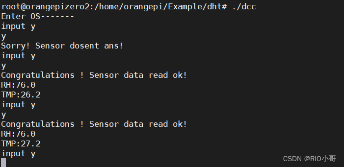
-
有没有办法让H616的核心板怎么既能用SDIO贴片flash加载系统,又能用TF卡的SDIO功能发布在 H/F/TV Series
如题,有没有办法让H616的核心板怎么既能用SDIO贴片flash加载系统,又能用TF卡的SDIO功能
-
BIGTREETECH CB1(H616)和 树莓派4B CPU对比测试发布在 H/F/TV Series
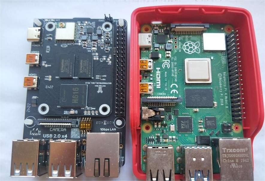
一,实物对比图:
BIGTREETECH CB1的底板接口的分布和树莓派4B是一样的,但是没有树莓派的音频接口,底板也不能放到树莓派4B的官方外壳里,因为底板的背面有一个DSI接口,高度超出了。
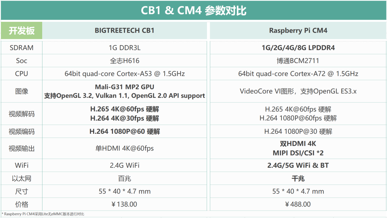
二,开发板硬件配置对比
可以看出H616为4核A53@1.5G,树莓派4B为4核A72@1.5G,树莓派4B的CPU规格略高一些,但它俩都是28nm制程工艺。
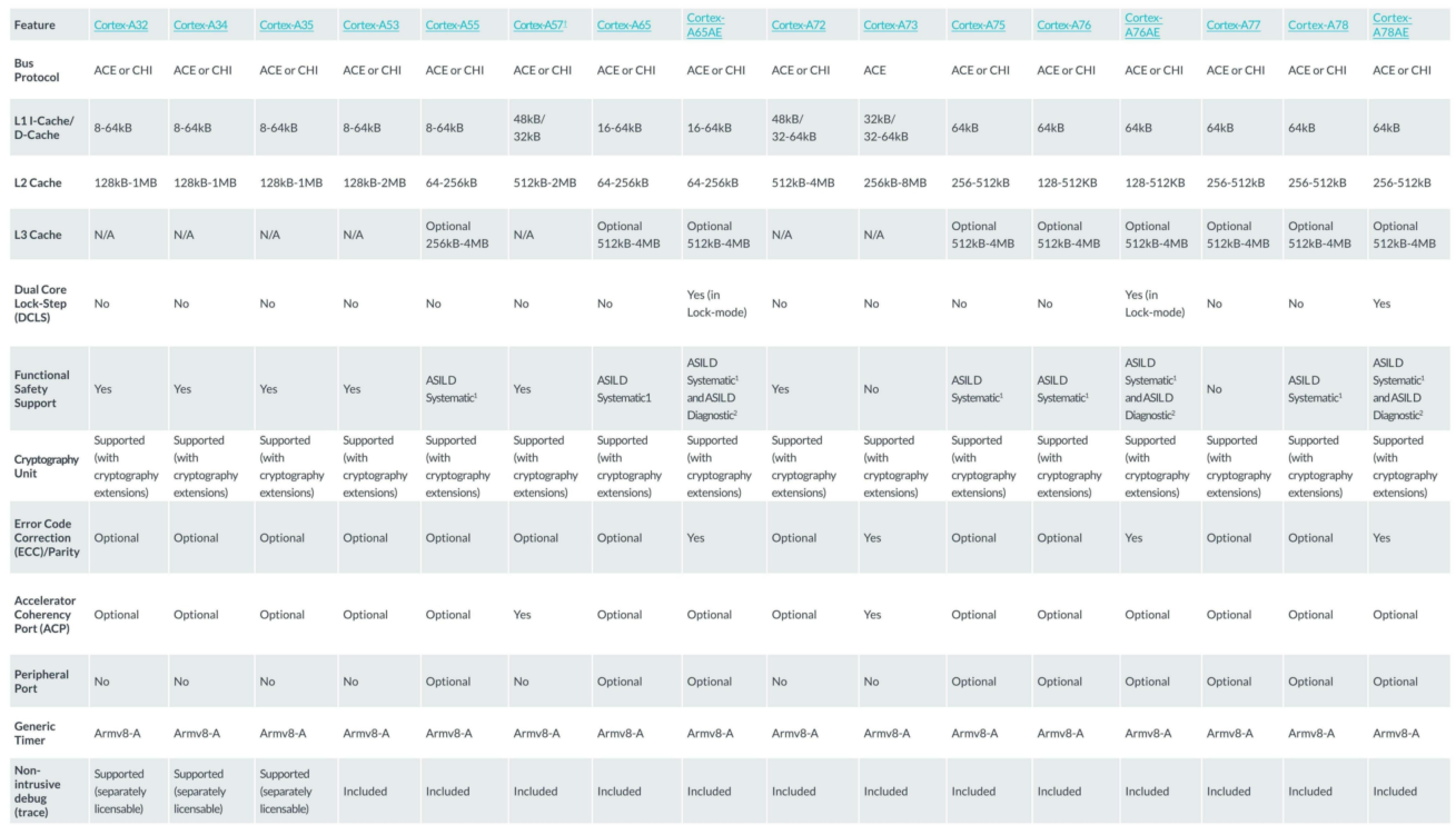
三,CPU规格对比:
这个上一个ARM官网的对比图。

四,室温下CPU温度对比
使用命令
cat /sys/class/thermal/thermal_zone0/temp | awk '{print $1/1000}'


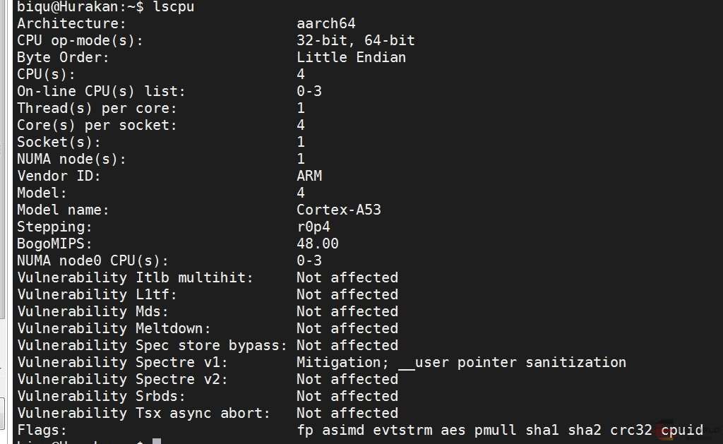
五,lscpu命令对比
其中可以看到H616的BogoMIPS是48,树莓派4B的BogoMIPS是108。
何为BogoMIPS,MIPS是millions of instructions per second(百万条指令每秒)的缩写,其代表CPU的运算速度,是cpu性能的重要指标。但只能用来粗略计算处理器的性能,并不十分精确。

六,专业软件对比CPU
这里我们使用Sysbench这个软件来测试2款CPU的性能。
Sysbench是一个开源的、模块化的、跨平台的多线程性能测试工具,可以用来进行CPU、内存、磁盘I/O、线程、数据库的性能测试。
安装使用命令
sudo apt-get install sysbench
测试CPU命令sysbench cpu runbiqu@Hurakan:~$ sysbench cpu run sysbench 1.0.20 (using system LuaJIT 2.1.0-beta3) Running the test with following options: Number of threads: 1 Initializing random number generator from current time Prime numbers limit: 10000 Initializing worker threads... Threads started! CPU speed: events per second: 502.43 General statistics: total time: 10.0008s total number of events: 5028 Latency (ms): min: 1.98 avg: 1.99 max: 2.19 95th percentile: 2.00 sum: 9995.01 Threads fairness: events (avg/stddev): 5028.0000/0.00 execution time (avg/stddev): 9.9950/0.00 biqu@Hurakan:~$ sysbench cpu run sysbench 1.0.20 (using system LuaJIT 2.1.0-beta3) Running the test with following options: Number of threads: 1 Initializing random number generator from current time Prime numbers limit: 10000 Initializing worker threads... Threads started! CPU speed: events per second: 502.85 General statistics: total time: 10.0005s total number of events: 5032 Latency (ms): min: 1.98 avg: 1.99 max: 2.20 95th percentile: 2.00 sum: 9995.15 Threads fairness: events (avg/stddev): 5032.0000/0.00 execution time (avg/stddev): 9.9951/0.00 biqu@Hurakan:~$
tage@raspberrypi:~ $ sysbench cpu run
sysbench 1.0.20 (using system LuaJIT 2.1.0-beta3)

Running the test with following options:
Number of threads: 1
Initializing random number generator from current time


Prime numbers limit: 10000

Initializing worker threads...

Threads started!

CPU speed:
    events per second:  1483.27

General statistics:
    total time:                          10.0005s
    total number of events:              14840

Latency (ms):
         min:                                    0.67
         avg:                                    0.67
         max:                                    1.81
         95th percentile:                        0.68
         sum:                                 9994.28

Threads fairness:
    events (avg/stddev):           14840.0000/0.00
    execution time (avg/stddev):   9.9943/0.00

tage@raspberrypi:~ $
其中CPU speed: events per second:CPU速度:每秒完成数 是衡量CPU速度的指标,可以看到在单线程下,BIGTREETECH CB1是502.85,树莓派4B是1483.27。
总结:通过对2种开发板CPU进行各种对比,可以发现H616和树莓派4B在CPU性能上还是有一定差距的。
-
LVGL视频播放界面实现方法发布在 GUI
1.主题
LVGL视频播放界面实现方法
2.问题背景
使用LVGL开发且需要在UI下显示视频或者显示摄像头数据,但是不知道如何实现,要么是只显示UI,要么就只显示视频。
3.具体表现
可以看下视频播放的时候有哪些元素。

有播放按钮,进度条,设置等可交互的控件,这些都位于UI层。
UI的下方就是视频解码后的一帧数据,视频数据位于视频层。
4.问题分析
一般UI层位于视频层的上方,如果UI层没有设置透明度,那么会有一个背景色,覆盖了视频层,导致只能看到背景色和一些控制按钮。
5.根本原因
首先需要知道有图层的概念,下面的命令可以看到图层的信息:
root@TinaLinux:/# cat /sys/class/disp/disp/attr/sys
screen 0:
de_rate 300000000 hz, ref_fps:59
mgr0: 1280x800 fmt[rgb] cs[0x204] range[full] eotf[0x4] bits[8bits] err[1] force_sync[1] unblank direct_show[false] iommu[1]
dmabuf: cache[4] cache max[4] umap skip[0] umap skip max[18]
        lcd output      backlight( 50)  fps:60.0        1280x 800
        err:0   skip:67 irq:2300        vsync:0 vsync_skip:0
   BUF    enable ch[0] lyr[0] z[0] prem[N] a[pixel   0] fmt[ 77] fb[1280, 736; 640, 368; 640, 368] crop[   0,   0,1280, 720] frame[   0,   0,1280, 800] addr[fb200000,fb2e6000,fb359000] flags[0x       0] trd[0,0]
depth[ 0]    BUF    enable ch[1] lyr[0] z[16] prem[N] a[pixel 255] fmt[  0] fb[1280, 800;1280, 800;1280, 800] crop[   0,   0,1280, 800] frame[   0,   0,1280, 800] addr[ff800000,       0,       0] flags[0x
  0] trd[0,0]
在内核初始化过程中,显示驱动注册/dev/fb0,会申请UI层,可以看到ch[1] lyr[0],一般UI就一个地址addr[ff800000, 0, 0],并且也是最顶层的z[16],混合模式a[pixel 255]表示由应用控制UI层的透明度。
视频播放(使用TPlayer接口)的时候会通过中间件申请视频图层,可以看到ch[0] lyr[0],并且yuv三个地址一直在变化addr[fb200000,fb2e6000,fb359000],通常视频会放到最底层z[0]。
当应用没有透明时,因为UI层的zorder比视频层大,因此只能看到UI,看不到视频,所以应用需要“挖空”。
6.解决办法
下面代码里的屏幕,一般是指/dev/fb0,LVGL版本是8.3.2。
使用下面的代码前需要在lv_conf.h中设置参数:
#define LV_COLOR_SCREEN_TRANSP 1/* 初始化屏幕风格 */ static lv_style_t style_scr_act; if (style_scr_act.prop_cnt == 0) { lv_style_init(&style_scr_act); /* 默认不是透明的,后面按需要切换即可 */ lv_style_set_bg_opa(&style_scr_act, LV_OPA_COVER); /* 一定要应用风格,不然也是没有效果的 */ lv_obj_add_style(lv_scr_act(), &style_scr_act, 0); } /* 这里根据按钮状态,切换不同风格,一种是UI能够透明看到底下的视频,一种是UI覆盖视频,视频就看不到了 */ if (lv_obj_has_state(btn, LV_STATE_CHECKED)) { /* 这里切换为UI透明 */ lv_label_set_text(label, "Stop"); /* 这里设置屏幕是透明的 */ lv_disp_get_default()->driver->screen_transp = 1; /* 这里设置屏幕背景是透明的 */ lv_disp_set_bg_opa(lv_disp_get_default(), LV_OPA_TRANSP); /* 这里清空屏幕,不清空的话,可能不会生效 */ lv_memset_00(lv_disp_get_default()->driver->draw_buf->buf_act, lv_disp_get_default()->driver->draw_buf->size * sizeof(lv_color32_t)); /* 这里屏幕风格切换为透明的 */ lv_style_set_bg_opa(&style_scr_act, LV_OPA_TRANSP); /* 通知风格变化,需要更新 */ lv_obj_report_style_change(&style_scr_act); } else { /* 这里切换为UI不透明,也就是覆盖视频 */ lv_label_set_text(label, "Play"); /* 这里设置屏幕是不透明的 */ lv_disp_get_default()->driver->screen_transp = 0; /* 这里设置屏幕背景是不透明的 */ lv_disp_set_bg_opa(lv_disp_get_default(), LV_OPA_COVER); /* 这里屏幕风格切换为不透明的 */ lv_style_set_bg_opa(&style_scr_act, LV_OPA_COVER); /* 通知风格变化,需要更新 */ lv_obj_report_style_change(&style_scr_act); }
-
创龙AD+全志T3 ad_display 开发案例发布在 创龙科技专区
前 言
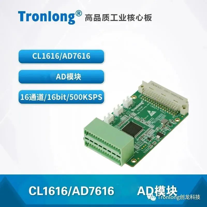
本文主要介绍基于全志科技T3(ARM Cortex-A7)处理器的8/16通道AD采集开发案例,使用核芯互联CL1606/CL1616AD芯片,亦适用于ADI AD7606/AD7616。CL1606/CL1616与AD7606/AD7616软硬件兼容。
备注:
(1)创龙科技TL7606I模块使用AD芯片为核芯互联CL1606或ADI AD7606,两者均测试通过,且测试步骤无差别。
(2)创龙科技TL7616P模块使用AD芯片为核芯互联CL1616或ADI AD7616,两者均测试通过,且测试步骤无差别。
硬件平台:
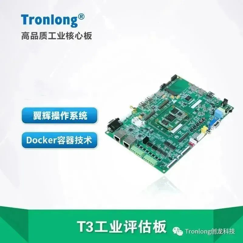
创龙科技T3工业评估板
TL7606I多通道AD模块

TL7616P多通道AD模块
1 ad_display案例
1.1 案例说明
案例功能:评估板通过SPI接口,使用创龙科技TL7606I/TL7616P模块采集8通道或16通道数据,并通过Qt显示波形。
案例支持如下2种模式:- 单步模式:程序将会采集1024个数据后,显示静态波形。
- 连续模式:程序将会连续采集数据,并实时显示动态波形。
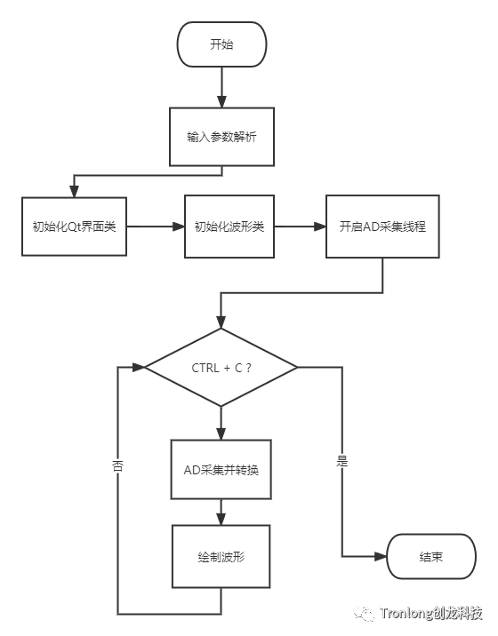
程序流程如下图所示。
1.2 案例测试
1.2.1 TL7606I模块测试
(1)硬件连接。
请使用VGA线将评估板VGA OUT接口与VGA显示屏连接。
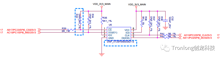
由于评估底板拓展接口未预留SPI总线引脚,因此需参考如下方法进行飞线,并且应尽可能使用短线连接,硬件连接如下图所示。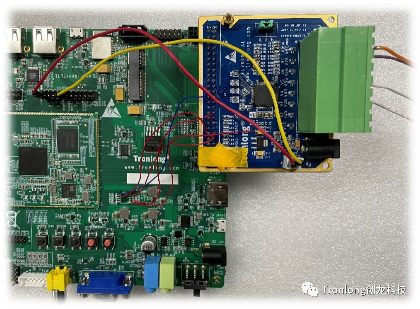
将评估底板SPI FLASH(U6)空贴后的引脚1(SPI CS)、2(SPI MISO)、5(SPI MOSI)、6(SPI CLK)和4(GND)通过飞线引出。
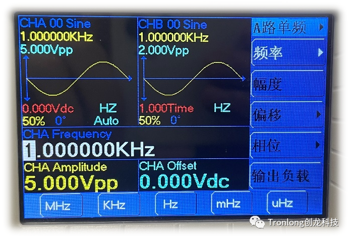
案例支持TL7606I模块8通道同时采集与显示。本次测试以TL7606I模块V4和V7通道为例,请将TL7606I模块的V4和V7通道分别正确连接至信号发生器A通道和B通道。信号发生器设置A通道输出频率为1KHz、峰峰值为5Vpp(即幅值为2.5V)的正弦波信号,B通道输出频率为1KHz、峰峰值为2Vpp(即幅值为1V)的正弦波信号,如下图所示。待测信号电压请勿超过模块量程,否则可能会导致模块损坏。
(2)案例测试。
为确保Qt程序运行的流畅性,评估板将使用eMMC启动模式进行测试,请确保eMMC已固化最新系统。
请先取出Linux系统启动卡,根据底板丝印将启动方式选择拨码开关拨为0,将评估板上电,系统将从eMMC启动。
请将案例bin目录下的可执行文件ad_display、"driver\boot_package"目录下的boot_package_vga_ad7606.fex镜像文件和"driver\bin"目录下的ad76x6.ko驱动文件拷贝至评估板文件系统任意目录下。同时,将案例"qwt\libqwt-6.1.3"目录下的所有文件拷贝至评估板文件系统"/usr/local/Qt-5.9.0/lib/"目录下。
在评估板文件系统boot_package_vga_ad7606.fex镜像文件所在路径下,执行如下命令将其固化至eMMC,并重启系统。
Target# dd if=boot_package_vga_ad7606.fex of=/dev/mmcblk0 seek=32800
Target# dd if=boot_package_vga_ad7606.fex of=/dev/mmcblk0 seek=24576
Target# sync
Target# reboot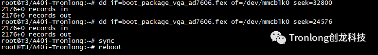
评估板系统重启后,进入评估板文件系统执行如下命令加载驱动。加载成功后,将会生成设备节点"/dev/ad7606"。
Target# insmod ad76x6.ko
Target# ls /dev/ad7606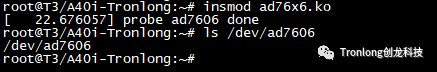
执行如下命令,关闭默认运行的Qt GUI显示,并使能Qt程序运行环境。
Target# killall Launcher
Target# killall -9 MediaUI
Target# killall -9 CameraUI
Target# fbinit
Target# echo 0,0 > /sys/class/disp/disp/attr/fb2ui
Target# source /qt5.9.sh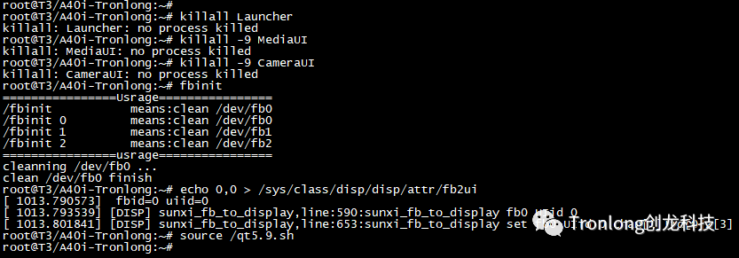
执行如下命令,查询程序运行参数。
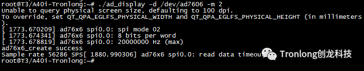
Target# ./ad_display --help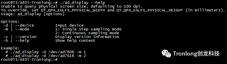
a)单步模式
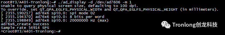
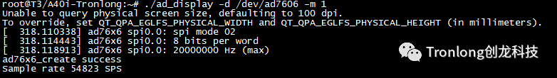
执行如下命令,以单步模式采集数据。Target# ./ad_display -d /dev/ad7606 -m 1参数解析:
-d:指定设备节点;
-m:选择运行模式(1表示单步模式,2表示连续模式)。同时,VGA显示屏将会显示静态波形,如下图所示。

按下"Ctrl + C"可停止程序运行。
b)连续模式
执行如下命令,以连续模式采集数据。Target# ./ad_display -d /dev/ad7606 -m 2同时,VGA显示屏将会实时显示动态波形,如下图所示。
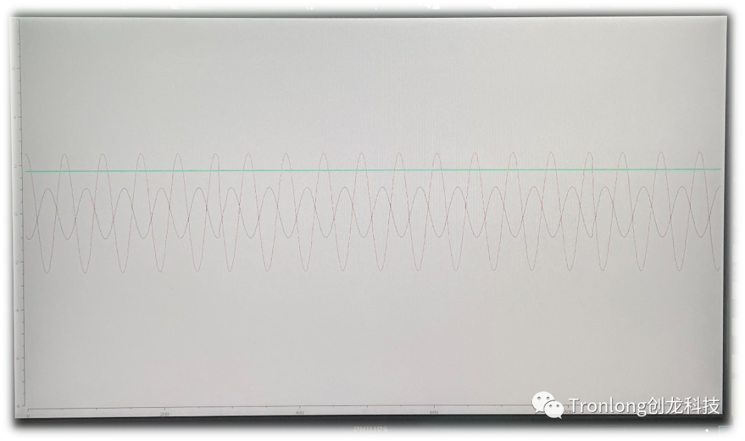
程序运行过程中,CPU占用率约为26%。
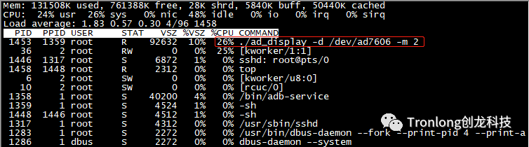
按下"Ctrl + C"可停止程序运行。
-
看到一篇V853开发板nfs配置方法,分享一下发布在 V Series
原文链接:http://bbs.eeworld.com.cn/thread-1220718-1-1.html
作者:dql2016网络文件系统,英文 Network File System(NFS),是由 SUN 公司研制的 UNIX 表示层协议 (presentation layer protocol),能使使用者访问网络上别处的文件就像在使用自己的计算机一样。 将Ubuntu文件目录挂载到开发板上就能方便的复制文件。
输入
make kernel_menuconfig选择File System->Network File System,如下配置
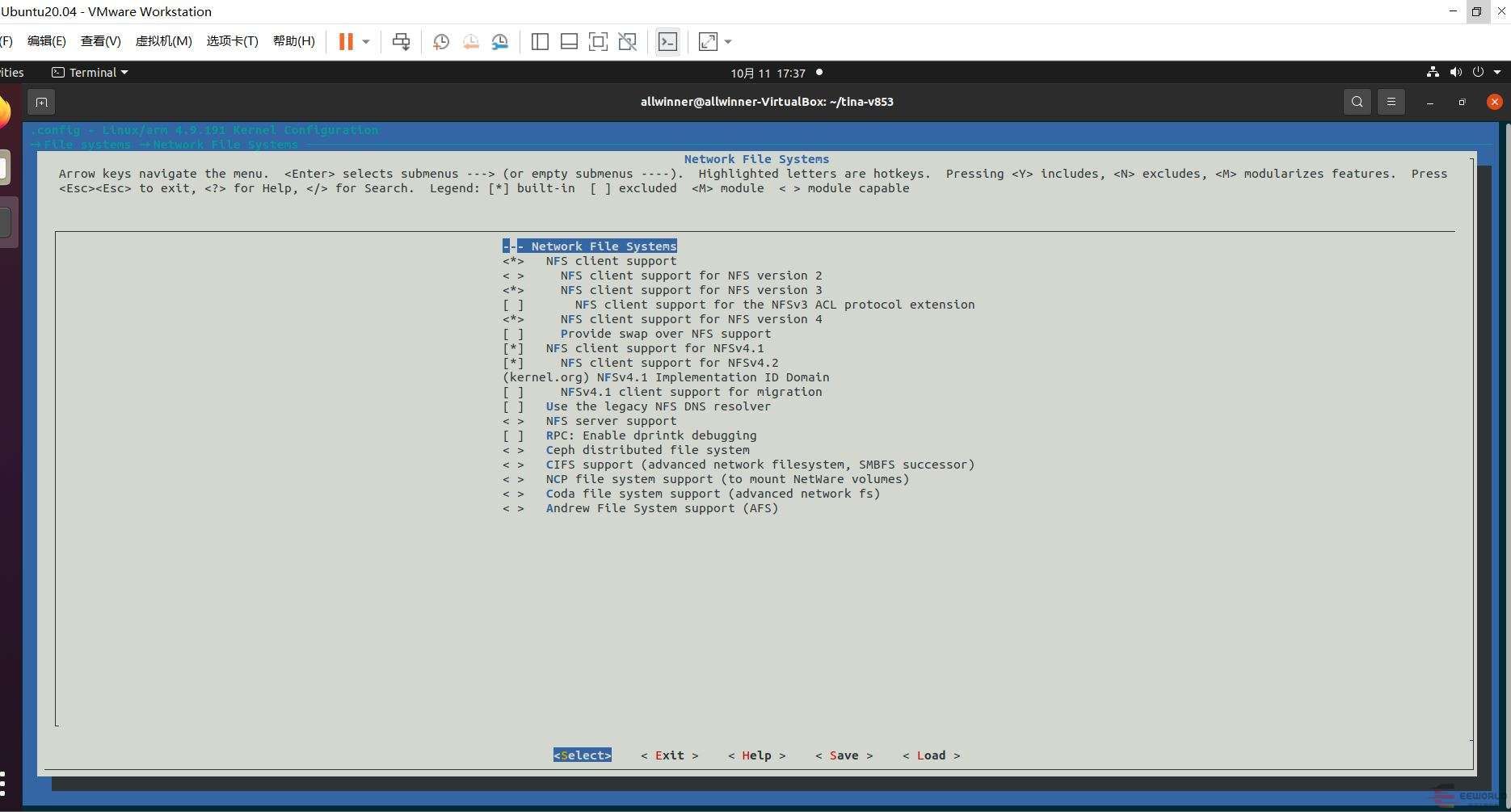
重新编译并打包内核
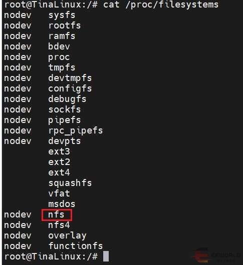
make -j4
pack
查看
cat /proc/filesystems支持的文件系统,发现多了两个nfs和nfs4
ubuntu配置
安装 NFS 软件包
sudo apt-get install nfs-kernel-server  # 安装 NFS服务器端
sudo apt-get install nfs-common         # 安装 NFS客户端
添加 NFS 共享目录
sudo gedit /etc/exports若需要把 “/home/allwinner/nfsroot” 目录设置为 NFS 共享目录,请在该文件末尾添加下面的一行:
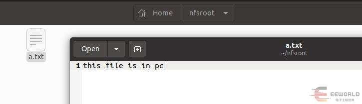
/home/allwinner/nfsroot *(rw,sync,no_root_squash) # * 表示允许任何网段 IP 的系统访问该 NFS 目录新建“/nfsroot”目录,并为该目录设置最宽松的权限:
mkdir /home/allwinner/nfsroot
sudo chmod -R 777 /home/allwinner/nfsroot
测试文件
启动 NFS 服务
sudo /etc/init.d/nfs-kernel-server restart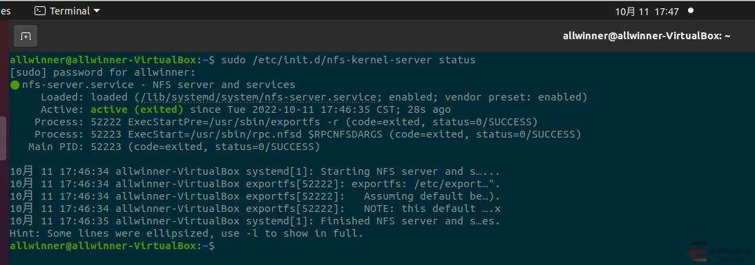
开发板上挂载
mount -o nolock -t nfs 192.168.8.65:/home/allwinner/nfsroot /mnt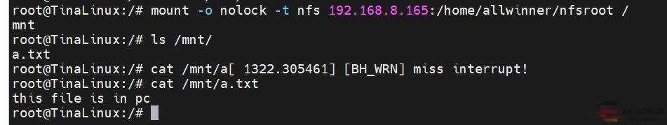
-
repo安装报错 /usr/bin/env: “python”: 没有那个文件或目录 解决方法发布在 V Series
转自:http://bbs.eeworld.com.cn/thread-1219304-1-1.html
根据全志 V853 SDK 下载环境搭建,安装repo时出现如下错误:
repo help
/usr/bin/env: “python”: 没有那个文件或目录
解决方案:
出现这个错误是由于在电脑中没有安装python,或者是因为安装了python2但是没有创建python2到python的软链接;
注意:一定要安装python2,使用python3不行。
如果没有安装python直接使用如下命令安装就行:
sudo apt-get install python如果安装了python2,只要使用如下命令创建软链接就行:
sudo ln -s /usr/bin/python2 /usr/bin/pythonrepo 正确配置好后,输入repo help的打印如下:
repo help
warning: Python 3 support is currently experimental. YMMV.
Please use Python 2.6 - 2.7 instead.
usage: repo COMMAND [ARGS]

repo is not yet installed.  Use "repo init" to install it here.

The most commonly used repo commands are:

  init      Install repo in the current working directory
  help      Display detailed help on a command

For access to the full online help, install repo ("repo init").