使用 LicheeRV 86 Panel 与 Tina BSP 实现 RGB 与 SPI 双屏显示
-
Tina 提供了2种 SPI TFT 显示屏的驱动方式。第一种是官方推荐的
fbdev方式,使用Framebuffer implementaion without display hardware of AW进行 SPI屏幕的驱动。另外一种是使用fbtft进行 SPI 屏幕驱动。fbdev方式由于pinctrl在新内核中调用方式出现修改,所以暂时无法使用。修改难度较大。fbtft虽然官方wiki表明不建议在 Linux 5.4 中使用,但是其实也是可以使用的,只需要修改一下 GPIO 的注册方式就行。先驱动 SPI 屏幕
这里驱动的屏幕所选择的是 ST7789V SPI
修改 FBTFT 驱动
进入
tina-d1-open/lichee/linux-5.4/drivers/staging/fbtft找到fbtft-core.c首先加入将要使用到的头文件
#include <linux/gpio.h>
#include <linux/of_gpio.h>
然后找到
static int fbtft_request_one_gpio()函数,将已经弃用的端口绑定方法改为以下内容static int fbtft_request_one_gpio(struct fbtft_par *par, const char *name, int index, struct gpio_desc **gpiop) { struct device *dev = par->info->device; struct device_node *node = dev->of_node; int gpio, flags, ret = 0; enum of_gpio_flags of_flags; if (of_find_property(node, name, NULL)) { gpio = of_get_named_gpio_flags(node, name, index, &of_flags); if (gpio == -ENOENT) return 0; if (gpio == -EPROBE_DEFER) return gpio; if (gpio < 0) { dev_err(dev, "failed to get '%s' from DT\n", name); return gpio; } flags = (of_flags & OF_GPIO_ACTIVE_LOW) ? GPIOF_OUT_INIT_LOW : GPIOF_OUT_INIT_HIGH; ret = devm_gpio_request_one(dev, gpio, flags, dev->driver->name); if (ret) { dev_err(dev, "gpio_request_one('%s'=%d) failed with %d\n", name, gpio, ret); return ret; } *gpiop = gpio_to_desc(gpio); fbtft_par_dbg(DEBUG_REQUEST_GPIOS, par, "%s: '%s' = GPIO%d\n", __func__, name, gpio); } return ret; }找到
static void fbtft_reset()函数,将 RST 信号最后拉高static void fbtft_reset(struct fbtft_par *par) { if (!par->gpio.reset) return; fbtft_par_dbg(DEBUG_RESET, par, "%s()\n", __func__); gpiod_set_value_cansleep(par->gpio.reset, 1); msleep(10); gpiod_set_value_cansleep(par->gpio.reset, 0); msleep(200); gpiod_set_value_cansleep(par->gpio.reset, 1); msleep(10); }找到
static void fbtft_set_addr_win()函数,添加地址偏移。否则会出现下图部分雪花屏现象。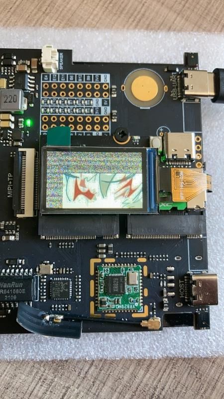
static void fbtft_set_addr_win(struct fbtft_par *par, int xs, int ys, int xe,
			       int ye)
{
	switch(par->info->var.rotate)
	{
		case   0: xs+=53;xe+=53;ys+=40;ye+=40;
				 break;
		case  90: xs+=40;xe+=40;ys+=53;ye+=53;
				 break;
		case 180: xs+=53;xe+=53;ys+=40;ye+=40;
				 break;
		case 270: xs+=40;xe+=40;ys+=53;ye+=53;
				 break;
		default :
				 break;
	}

	write_reg(par, MIPI_DCS_SET_COLUMN_ADDRESS,
		  (xs >> 8) & 0xFF, xs & 0xFF, (xe >> 8) & 0xFF, xe & 0xFF);

	write_reg(par, MIPI_DCS_SET_PAGE_ADDRESS,
		  (ys >> 8) & 0xFF, ys & 0xFF, (ye >> 8) & 0xFF, ye & 0xFF);

	write_reg(par, MIPI_DCS_WRITE_MEMORY_START);
}
找到
fb_st7789v.c,参照STM32的初始化函数对初始化部分进行修改。static int init_display(struct fbtft_par *par) { par->fbtftops.reset(par); mdelay(50); write_reg(par,0x36,0x00); write_reg(par,0x3A,0x05); write_reg(par,0xB2,0x0C,0x0C,0x00,0x33,0x33); write_reg(par,0xB7,0x35); write_reg(par,0xBB,0x19); write_reg(par,0xC0,0x2C); write_reg(par,0xC2,0x01); write_reg(par,0xC3,0x12); write_reg(par,0xC4,0x20); write_reg(par,0xC6,0x0F); write_reg(par,0xD0,0xA4,0xA1); write_reg(par,0xE0,0xD0,0x04,0x0D,0x11,0x13,0x2B,0x3F,0x54,0x4C,0x18,0x0D,0x0B,0x1F,0x23); write_reg(par,0xE1,0xD0,0x04,0x0C,0x11,0x13,0x2C,0x3F,0x44,0x51,0x2F,0x1F,0x1F,0x20,0x23); write_reg(par,0x21); write_reg(par,0x11); mdelay(50); write_reg(par,0x29); mdelay(200); return 0; }将屏幕大小配置为屏幕实际大小
static struct fbtft_display display = {
	.regwidth = 8,
	.width = 135,
	.height = 240,
	.gamma_num = 2,
	.gamma_len = 14,
	.gamma = DEFAULT_GAMMA,
	.fbtftops = {
		.init_display = init_display,
		.set_var = set_var,
		.set_gamma = set_gamma,
		.blank = blank,
	},
};
设备树修改
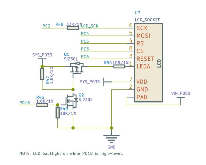
首先打开电路图,找到 SPI 屏幕的电路。
根据电路,找到
pio节点,添加 SPI0 所用引脚,spi0_pins_a作为数据时钟绑定,spi0_pins_b作为 CS 的绑定,并上拉。RST,DC,背光在这里不做声明。spi0_pins_a: spi0@0 { pins = "PC2", "PC4"; function = "spi0"; drive-strength = <10>; }; spi0_pins_b: spi0@1 { pins = "PC3"; function = "spi0"; drive-strength = <10>; bias-pull-up; };然后找到 SPI0 节点,添加屏幕使用的设备树。使用
pinctrl-0将pio中定义的 SPI 引脚进行注册。RST,DC,背光在这里进行绑定,并设置其工作电平。&spi0 { clock-frequency = <100000000>; pinctrl-0 = <&spi0_pins_a &spi0_pins_b>; status = "okay"; st7789v@0 { status = "okay"; compatible = "sitronix,st7789v"; reg = <0>; spi-max-frequency = <32000000>; rotate = <90>; rgb; fps = <30>; buswidth = <8>; reset = <&pio PC 6 GPIO_ACTIVE_LOW>; dc = <&pio PC 5 GPIO_ACTIVE_LOW>; led = <&pio PD 18 GPIO_ACTIVE_HIGH>; debug = <1>; }; };最后,将不需要的屏幕关闭,方便调试
&disp {
	disp_init_enable = <0>;
    ......
}

&lcd0 {
	lcd_used = <0>;
    ......
}

&hdmi {
	hdmi_used = <0>;
    ......
}
内核配置
进入
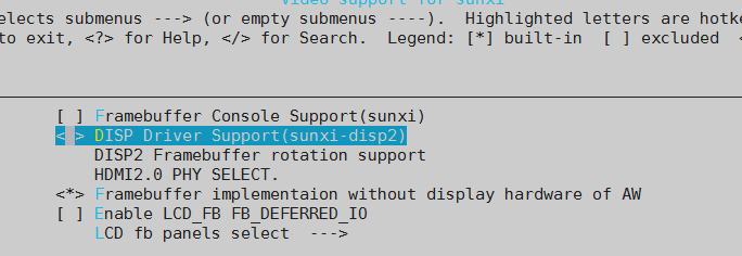
kernel_menuconfig,开启 FBTFT,关闭 RGB,MIPI 所使用的DISP Driver Support(sunxi-disp2)输出。Device Drivers ---> Graphics support ---> Frame buffer Devices ---> <*> Support for frame buffer devices ---> Video support for sunxi ---> < > DISP Driver Support(sunxi-disp2) [*] Staging drivers ---> <*> Support for small TFT LCD display modules ---> <*> FB driver for the ST7789V LCD Controller由于上面配置关闭了
DISP Driver Support(sunxi-disp2),所用需要在menuconfig里将内核模块关闭,否则会出现找不到驱动的错误。Kernel modules ---> Video Support ---> < > kmod-sunxi-disp....................................... sunxi-disp support < > kmod-sunxi-g2d......................................... sunxi-g2d support < > kmod-sunxi-hdmi....................................... sunxi-hdmi support < > kmod-sunxi-uvc......................................... sunxi-uvc support编译,打包,使用
fbviewer进行测试make -j65535 pack fbviewer Yuzuki.jpg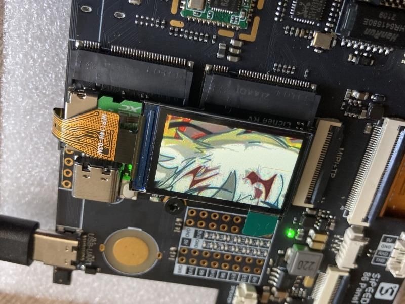
修改为双屏驱动
修改双屏也很简单,SPI 屏幕调试完成之后,将刚才关闭的各类驱动打开即可。
配置设备树
找到 SPI0 节点,将背光
led注释掉,查看电路图可知 RGB 屏幕和 SPI 屏幕使用的背光是同一个,这里不需要分开注册。&spi0 { clock-frequency = <100000000>; pinctrl-0 = <&spi0_pins_a &spi0_pins_b>; status = "okay"; st7789v@0 { status = "okay"; compatible = "sitronix,st7789v"; reg = <0>; spi-max-frequency = <32000000>; rotate = <90>; rgb; fps = <30>; buswidth = <8>; reset = <&pio PC 6 GPIO_ACTIVE_LOW>; dc = <&pio PC 5 GPIO_ACTIVE_LOW>; // led = <&pio PD 18 GPIO_ACTIVE_HIGH>; debug = <1>; }; };把之前关闭的显示输出重新打开
&disp {
	disp_init_enable = <1>;
    ......
}

&lcd0 {
	lcd_used = <1>;
    ......
}

&hdmi {
	hdmi_used = <1>;
    ......
}
配置内核
进入
kernel_menuconfig,开启DISP Driver Support(sunxi-disp2)输出,并选择面板驱动。Device Drivers ---> Graphics support ---> Frame buffer Devices ---> <*> Support for frame buffer devices ---> Video support for sunxi ---> <*> DISP Driver Support(sunxi-disp2) <*> HDMI2.0 Driver Support(sunxi-disp2) HDMI2.0 PHY SELECT. (Allwinner PHY) ---> LCD panels select ---> [*] LCD support ST7701S RGB panel [*] Staging drivers ---> <*> Support for small TFT LCD display modules ---> <*> FB driver for the ST7789V LCD Controller在
menuconfig里将内核模块重新打开。Kernel modules ---> Video Support ---> <*> kmod-sunxi-disp....................................... sunxi-disp support <*> kmod-sunxi-g2d......................................... sunxi-g2d support <*> kmod-sunxi-hdmi....................................... sunxi-hdmi support <*> kmod-sunxi-uvc......................................... sunxi-uvc support编译,打包,测试。这里使用
ffmpeg进行双屏播放badapple.mp4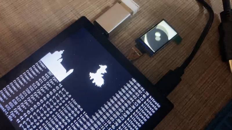
附录:部分设备树完整参考(配置双屏后,HDMI禁用了)
&pio { ...前略... spdif_pins_b: spdif_sleep@0 { pins = "PB0"; function = "io_disabled"; drive-strength = <20>; bias-disable; }; spi0_pins_a: spi0@0 { pins = "PC2", "PC4"; /*clk mosi*/ function = "spi0"; drive-strength = <10>; }; spi0_pins_b: spi0@1 { pins = "PC3"; function = "spi0"; drive-strength = <10>; bias-pull-up; // only CS should be pulled up }; spi1_pins_a: spi1@0 { pins = "PD11", "PD12", "PD13","PD14", "PD15"; /*clk mosi miso hold wp*/ function = "spi1"; drive-strength = <10>; }; spi1_pins_b: spi1@1 { pins = "PD10"; function = "spi1"; drive-strength = <10>; bias-pull-up; // only CS should be pulled up }; spi1_pins_c: spi1@2 { pins = "PD10", "PD11", "PD12", "PD13","PD14", "PD15"; function = "gpio_in"; drive-strength = <10>; }; ledc_pins_a: ledc@0 { pins = "PC0"; function = "ledc"; drive-strength = <10>; }; ledc_pins_b: ledc@1 { pins = "PC0"; function = "gpio_in"; }; ...后略... }; &spi0 { clock-frequency = <100000000>; pinctrl-0 = <&spi0_pins_a &spi0_pins_b>; status = "okay"; st7789v@0 { status = "okay"; compatible = "sitronix,st7789v"; reg = <0>; spi-max-frequency = <32000000>; rotate = <90>; rgb; fps = <30>; buswidth = <8>; reset = <&pio PC 6 GPIO_ACTIVE_LOW>; dc = <&pio PC 5 GPIO_ACTIVE_LOW>; // led = <&pio PD 18 GPIO_ACTIVE_HIGH>; debug = <1>; }; }; /*---------------------------------------------------------------------------------- disp init configuration disp_mode (0:screen0<screen0,fb0>) screenx_output_type (0:none; 1:lcd; 2:tv; 3:hdmi;5:vdpo) screenx_output_mode (used for hdmi output, 0:480i 1:576i 2:480p 3:576p 4:720p50) (5:720p60 6:1080i50 7:1080i60 8:1080p24 9:1080p50 10:1080p60) screenx_output_format (for hdmi, 0:RGB 1:yuv444 2:yuv422 3:yuv420) screenx_output_bits (for hdmi, 0:8bit 1:10bit 2:12bit 2:16bit) screenx_output_eotf (for hdmi, 0:reserve 4:SDR 16:HDR10 18:HLG) screenx_output_cs (for hdmi, 0:undefined 257:BT709 260:BT601 263:BT2020) screenx_output_dvi_hdmi (for hdmi, 0:undefined 1:dvi mode 2:hdmi mode) screen0_output_range (for hdmi, 0:default 1:full 2:limited) screen0_output_scan (for hdmi, 0:no data 1:overscan 2:underscan) screen0_output_aspect_ratio (for hdmi, 8-same as original picture 9-4:3 10-16:9 11-14:9) fbx format (4:RGB655 5:RGB565 6:RGB556 7:ARGB1555 8:RGBA5551 9:RGB888 10:ARGB8888 12:ARGB4444) fbx pixel sequence (0:ARGB 1:BGRA 2:ABGR 3:RGBA) fb0_scaler_mode_enable(scaler mode enable, used FE) fbx_width,fbx_height (framebuffer horizontal/vertical pixels, fix to output resolution while equal 0) lcdx_backlight (lcd init backlight,the range:[0,256],default:197 lcdx_yy (lcd init screen bright/contrast/saturation/hue, value:0~100, default:50/50/57/50) lcd0_contrast (LCD contrast, 0~100) lcd0_saturation (LCD saturation, 0~100) lcd0_hue (LCD hue, 0~100) framebuffer software rotation setting: disp_rotation_used: (0:disable; 1:enable,you must set fbX_width to lcd_y, set fbX_height to lcd_x) degreeX: (X:screen index; 0:0 degree; 1:90 degree; 3:270 degree) degreeX_Y: (X:screen index; Y:layer index 0~15; 0:0 degree; 1:90 degree; 3:270 degree) devX_output_type : config output type in bootGUI framework in UBOOT-2018. (0:none; 1:lcd; 2:tv; 4:hdmi;) devX_output_mode : config output resolution(see include/video/sunxi_display2.h) of bootGUI framework in UBOOT-2018 devX_screen_id : config display index of bootGUI framework in UBOOT-2018 devX_do_hpd : whether do hpd detectation or not in UBOOT-2018 chn_cfg_mode : Hardware DE channel allocation config. 0:single display with 6 channel, 1:dual display with 4 channel in main display and 2 channel in second display, 2:dual display with 3 channel in main display and 3 channel in second in display. ----------------------------------------------------------------------------------*/ &disp { disp_init_enable = <1>; disp_mode = <0>; screen0_output_type = <1>; screen0_output_mode = <4>; screen1_output_type = <3>; screen1_output_mode = <10>; screen1_output_format = <0>; screen1_output_bits = <0>; screen1_output_eotf = <4>; screen1_output_cs = <257>; screen1_output_dvi_hdmi = <2>; screen1_output_range = <2>; screen1_output_scan = <0>; screen1_output_aspect_ratio = <8>; dev0_output_type = <1>; dev0_output_mode = <4>; dev0_screen_id = <0>; dev0_do_hpd = <0>; dev1_output_type = <4>; dev1_output_mode = <10>; dev1_screen_id = <1>; dev1_do_hpd = <1>; def_output_dev = <0>; hdmi_mode_check = <1>; fb0_format = <0>; fb0_width = <0>; fb0_height = <0>; fb1_format = <0>; fb1_width = <0>; fb1_height = <0>; chn_cfg_mode = <1>; disp_para_zone = <1>; /*VCC-LCD*/ /* dc1sw-supply = <®_dc1sw>;*/ /*VCC-DSI*/ /* eldo3-supply = <®_eldo3>;*/ /*VCC-PD*/ /* dcdc1-supply = <®_dcdc1>;*/ }; /*---------------------------------------------------------------------------------- ;lcd0 configuration ;lcd_if: 0:hv(sync+de); 1:8080; 2:ttl; 3:lvds; 4:dsi; 5:edp; 6:extend dsi ;lcd_hv_if 0:Parallel RGB; 8:Serial RGB; 10:Dummy RGB; 11: RGB Dummy;12:CCIR656 ;lcd_hv_clk_phase 0:0 degree;1:90 degree;2:180 degree;3:270 degree ;lcd_hv_sync_polarity 0:vs low,hs low; 1:vs high,hslow; 2:vs low,hs high; 3:vs high,hs high ;lcd_hv_syuv_seq 0:YUYV; 1:YVYU; 2:UYVY; 3:VYUY ;lcd_cpu_if 0:18bit/1 cycle parallel(RGB666); 4:16bit/1cycle parallel (RGB565) ; 6:18bit/3 cycle parallel(RGB666); 7:16bit/2cycle parallel (RGB565) ;lcd_cpu_te 0:frame auto trigger; 1:frame triggered by te rising edge; 2:frame triggered by te falling edge; ;lcd_dsi_if 0:video mode; 1: Command mode; 2:video burst mode ;lcd_dsi_te 0:frame auto trigger; 1:frame triggered by te rising edge; 2:frame triggered by te falling edge; ;lcd_x: lcd horizontal resolution ;lcd_y: lcd vertical resolution ;lcd_width: width of lcd in mm ;lcd_height: height of lcd in mm ;lcd_dclk_freq: in MHZ unit ;lcd_pwm_freq: in HZ unit ;lcd_pwm_pol: lcd backlight PWM polarity ;lcd_pwm_max_limit lcd backlight PWM max limit(<=255) ;lcd_hbp: hsync back porch(pixel) + hsync plus width(pixel); ;lcd_ht: hsync total cycle(pixel) ;lcd_vbp: vsync back porch(line) + vysnc plus width(line) ;lcd_vt: vysnc total cycle(line) ;lcd_hspw: hsync plus width(pixel) ;lcd_vspw: vysnc plus width(pixel) ;lcd_lvds_if: 0:single link; 1:dual link ;lcd_lvds_colordepth: 0:8bit; 1:6bit ;lcd_lvds_mode: 0:NS mode; 1:JEIDA mode ;lcd_frm: 0:disable; 1:enable rgb666 dither; 2:enable rgb656 dither ;lcd_io_phase: 0:noraml; 1:intert phase(0~3bit: vsync phase; 4~7bit:hsync phase; ; 8~11bit:dclk phase; 12~15bit:de phase) ;lcd_gamma_en lcd gamma correction enable ;lcd_bright_curve_en lcd bright curve correction enable ;lcd_cmap_en lcd color map function enable ;deu_mode 0:smoll lcd screen; 1:large lcd screen(larger than 10inch) ;lcdgamma4iep: Smart Backlight parameter, lcd gamma vale * 10; ; decrease it while lcd is not bright enough; increase while lcd is too bright ;smart_color 90:normal lcd screen 65:retina lcd screen(9.7inch) ;Pin setting for special function ie.LVDS, RGB data or vsync ; name(donot care) = port:PD12<pin function><pull up or pull down><drive ability><output level> ;Pin setting for gpio: ; lcd_gpio_X = port:PD12<pin function><pull up or pull down><drive ability><output level> ;Pin setting for backlight enable pin ; lcd_bl_en = port:PD12<pin function><pull up or pull down><drive ability><output level> ;fsync setting, pulse to csi ;lcd_fsync_en (0:disable fsync,1:enable) ;lcd_fsync_act_time (active time of fsync, unit:pixel) ;lcd_fsync_dis_time (disactive time of fsync, unit:pixel) ;lcd_fsync_pol (0:positive;1:negative) ;gpio config: <&pio for cpu or &r_pio for cpus, port, port num, pio function, pull up or pull down(default 0), driver level(default 1), data> ;For dual link lvds: use lvds2link_pins_a and lvds2link_pins_b instead ;For rgb24: use rgb24_pins_a and rgb24_pins_b instead ;For lvds1: use lvds1_pins_a and lvds1_pins_b instead ;For lvds0: use lvds0_pins_a and lvds0_pins_b instead ;----------------------------------------------------------------------------------*/ &lcd0 { lcd_used = <1>; lcd_driver_name = "st7701s_rgb"; lcd_if = <0>; lcd_hv_if = <0>; lcd_width = <70>; lcd_height = <72>; lcd_x = <480>; lcd_y = <480>; lcd_dclk_freq = <19>; lcd_hbp = <60>; lcd_ht = <612>; lcd_hspw = <12>; lcd_vbp = <18>; lcd_vt = <520>; lcd_vspw = <4>; lcd_backlight = <50>; lcd_pwm_used = <1>; lcd_pwm_ch = <7>; lcd_pwm_freq = <20000>; lcd_pwm_pol = <1>; lcd_bright_curve_en = <0>; lcd_frm = <1>; lcd_io_phase = <0x0000>; lcd_gamma_en = <0>; lcd_cmap_en = <0>; lcd_hv_clk_phase= <0>; lcd_hv_sync_polarity= <0>; lcd_rb_swap = <0>; lcd_power = "vcc-lcd"; lcd_pin_power = "vcc-pd"; lcd_gpio_0 = <&pio PG 13 GPIO_ACTIVE_HIGH>; lcd_gpio_1 = <&pio PE 14 GPIO_ACTIVE_HIGH>; lcd_gpio_2 = <&pio PE 12 GPIO_ACTIVE_HIGH>; lcd_gpio_3 = <&pio PE 15 GPIO_ACTIVE_HIGH>; pinctrl-0 = <&rgb18_pins_a>; pinctrl-1 = <&rgb18_pins_b>; }; &hdmi { hdmi_used = <0>; hdmi_power_cnt = <0>; hdmi_cts_compatibility = <1>; hdmi_hdcp_enable = <1>; hdmi_hdcp22_enable = <0>; hdmi_cec_support = <1>; hdmi_cec_super_standby = <0>; ddc_en_io_ctrl = <0>; power_io_ctrl = <0>; }; -
@yuzukitsuru nb
-
本想调试一下st7789,发现tina 2.0 仍然不能用fbdev。
-
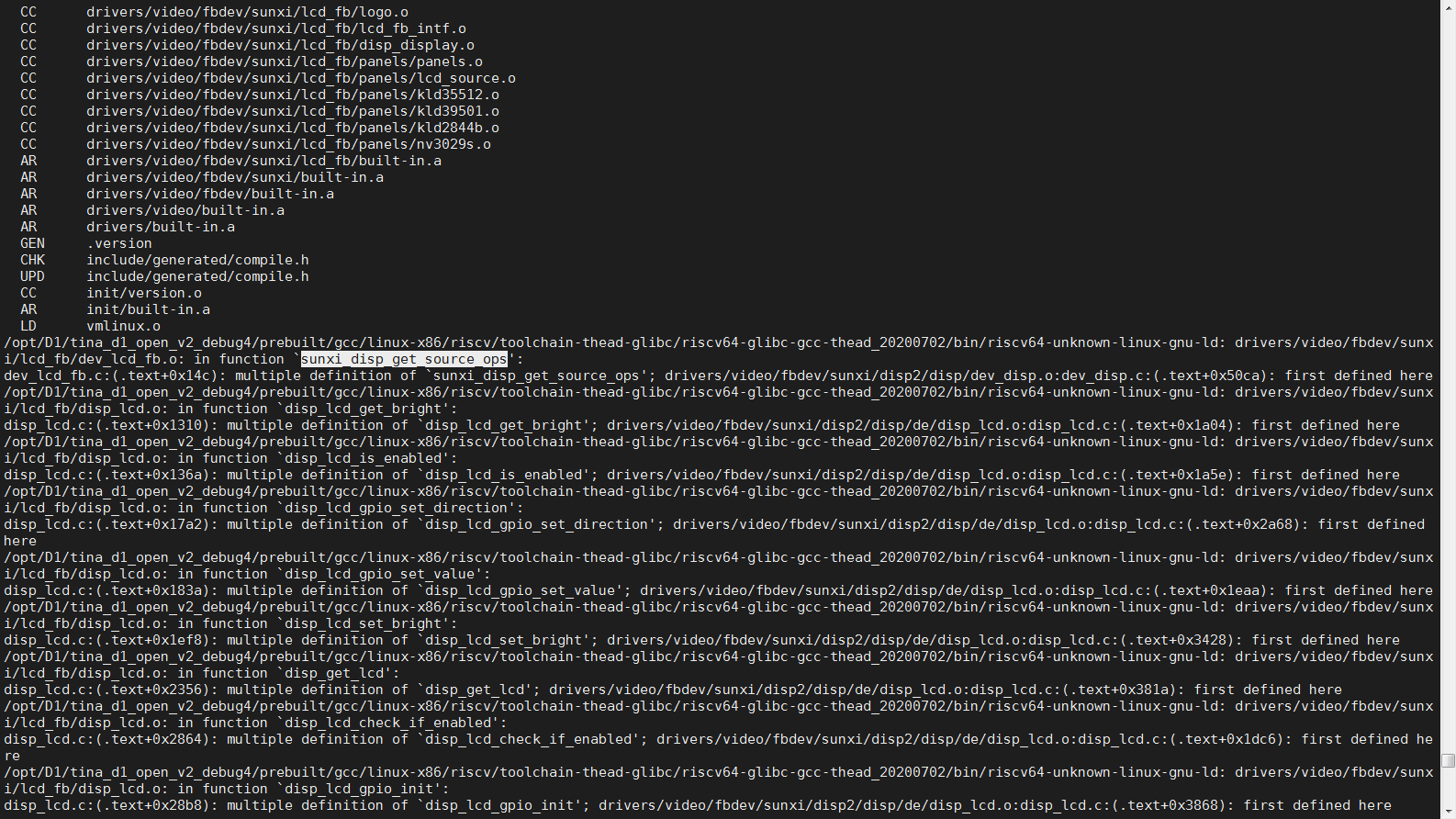
屏蔽 CONFIG_DISP2_SUNXI 之后,
CONFIG_LCD_FB: Framebuffer implementaion for LCD panel without DE and tcon
这个就可以编译成功了。
-
Referenced by
 q1215200171
 -
Referenced by q1215200171
-
大神,我在调试一款RGB屏 求指点一下 加qq 2250363061
Copyright © 2024 深圳全志在线有限公司 粤ICP备2021084185号 粤公网安备44030502007680号