A
awwwwa 发布的最佳帖子
-
回复: tina SDK ERROR: Dependence broken. Firmware maybe incorrect & cannot booting up...发布在 Linux
@hgs1975 This is not a error, you can normal boot up while showing this error. What's your hardware and how to configure it
-
回复: R128-S2 驱动 1024x600 RGB 显示屏 并运行 LVGL发布在 A Series
屏参改一下
lcd_driver_name = "default_lcd" lcd_backlight = 150 lcd_if = 0 lcd_x = 1024 lcd_y = 600 lcd_width = 150 lcd_height = 94 lcd_rb_swap = 0 lcd_dclk_freq = 48 lcd_pwm_used = 1 lcd_pwm_ch = 7 lcd_pwm_freq = 500000 lcd_pwm_pol = 1 lcd_hbp = 160 lcd_ht = 1344 lcd_hspw = 20 lcd_vbp = 20 lcd_vt = 635 lcd_vspw = 3 lcd_lvds_if = 0 lcd_lvds_colordepth = 1 lcd_lvds_mode = 0 lcd_frm = 0 lcd_io_phase = 0x0000 lcd_gamma_en = 0 lcd_bright_curve_en = 0 lcd_cmap_en = 0 -
回复: 只用的全志的板子,怎么才能往rootfs中添加文件发布在 Linux
target/allwinner/t113-nezha/base-files
target/allwinner/t113-nezha/busybox-init-base-files根据选择的overlay方式而定
-
回复: 如何将Libuvc编译到tina系统中发布在 V Series
参照opencv的编写使用cmake的makefile
include $(TOPDIR)/rules.mk PKG_NAME:=opencv PKG_VERSION:=4.1.1 PKG_RELEASE:=1 PKG_SOURCE_PROTO:=git PKG_SOURCE_URL:=https://github.com/opencv/opencv PKG_SOURCE_VERSION:=$(PKG_VERSION) PKG_MIRROR_HASH:=c8587820421d2f22acdafe4712d068ae490897dc445bdb4aa128ecaa8e65d3a1 PKG_MAINTAINER:= PKG_LICENSE:=BSD-3-Clause PKG_LICENSE_FILES:=LICENSE CMAKE_INSTALL:=1 CMAKE_BINARY_SUBDIR:=build PKG_BUILD_PARALLEL:=1 PKG_USE_MIPS16:=0 include $(INCLUDE_DIR)/package.mk include $(INCLUDE_DIR)/cmake.mk define Package/opencv/Default/description OpenCV (Open Source Computer Vision Library) is an open source computer vision and machine learning software library. OpenCV was built to provide a common infrastructure for computer vision applications and to accelerate the use of machine perception in the commercial products. Being a BSD-licensed product, OpenCV makes it easy for businesses to utilize and modify the code. endef define Package/opencv SECTION:=libs CATEGORY:=Libraries TITLE:=OpenCV URL:=https://opencv.org/ DEPENDS:=+libpthread +librt +libatomic +libstdcpp +zlib +libjpeg +python3 +python3-numpy endef CMAKE_OPTIONS += \ -DBUILD_opencv_gpu:BOOL=OFF \ -DWITH_1394:BOOL=OFF -DBUILD_opencv_stitching:BOOL=OFF \ -DBUILD_opencv_superres:BOOL=OFF -DBUILD_opencv_ts:BOOL=OFF \ -DBUILD_opencv_highgui:BOOL=ON \ -DBUILD_opencv_videostab:BOOL=OFF \ -DWITH_FFMPEG:BOOL=OFF \ -DWITH_GSTREAMER:BOOL=OFF \ -DWITH_LIBV4L:BOOL=ON \ -DWITH_PNG:BOOL=OFF \ -DWITH_GTK:BOOL=OFF \ -DWITH_TIFF:BOOL=OFF \ -DCMAKE_VERBOSE:BOOL=OFF \ -DENABLE_PRECOMPILED_HEADERS=OFF \ -DPYTHON3_INCLUDE_PATH=$(STAGING_DIR)/usr/include/python3.9 \ -DPYTHON3_LIBRARIES=$(STAGING_DIR)/usr/lib/libpython3.9.so \ -DPYTHON3_NUMPY_INCLUDE_DIRS=$(TARGET_ROOTFS_DIR)/pypi/numpy-1.20.1/ipkg-install/usr/lib/python3.9/site-packages/numpy/core/include \ -DBUILD_OPENCV_PYTHON3:BOOL=ON TARGET_LDFLAGS += -latomic define Package/opencv/install $(INSTALL_DIR) $(1)/usr/lib $(CP) $(PKG_INSTALL_DIR)/usr/lib/* $(1)/usr/lib/ endef $(eval $(call BuildPackage,opencv)) -
回复: LVGL 与 SPI TFT GUI案例报错发布在 A Series
https://r128.docs.aw-ol.com/others/faq/#_3
建议 删除 PMU 相关配置
[pmu] pmu_irq_pin = port:PA14<14><0><default><default> pmu_irq_wakeup = 2 pmu_hot_shutdown = 1 pmu_bat_unused = 0 pmu_usbad_vol = 4600 pmu_usbad_cur = 1500 pmu_usbpc_vol = 4600 pmu_usbpc_cur = 500 pmu_chg_ic_temp = 0 pmu_battery_rdc = 100 pmu_battery_cap = 3568 pmu_runtime_chgcur = 900 pmu_suspend_chgcur = 1200 pmu_shutdown_chgcur = 1200 pmu_init_chgvol = 4200 pmu_init_chg_pretime = 50 pmu_init_chg_csttime = 1200 pmu_chgled_type = 0 pmu_init_bc_en = 1 pmu_bat_temp_enable = 0 pmu_bat_charge_ltf = 2261 pmu_bat_charge_htf = 388 pmu_bat_shutdown_ltf = 3200 pmu_bat_shutdown_htf = 237 pmu_bat_para[0] = 0 pmu_bat_para[1] = 0 pmu_bat_para[2] = 0 pmu_bat_para[3] = 0 pmu_bat_para[4] = 0 pmu_bat_para[5] = 0 pmu_bat_para[6] = 1 pmu_bat_para[7] = 1 pmu_bat_para[8] = 2 pmu_bat_para[9] = 4 pmu_bat_para[10] = 5 pmu_bat_para[11] = 12 pmu_bat_para[12] = 19 pmu_bat_para[13] = 32 pmu_bat_para[14] = 41 pmu_bat_para[15] = 45 pmu_bat_para[16] = 48 pmu_bat_para[17] = 51 pmu_bat_para[18] = 54 pmu_bat_para[19] = 59 pmu_bat_para[20] = 63 pmu_bat_para[21] = 68 pmu_bat_para[22] = 71 pmu_bat_para[23] = 74 pmu_bat_para[24] = 78 pmu_bat_para[25] = 81 pmu_bat_para[26] = 82 pmu_bat_para[27] = 84 pmu_bat_para[28] = 88 pmu_bat_para[29] = 92 pmu_bat_para[30] = 96 pmu_bat_para[31] = 100 pmu_bat_temp_para[0] = 7466 pmu_bat_temp_para[1] = 4480 pmu_bat_temp_para[2] = 3518 pmu_bat_temp_para[3] = 2786 pmu_bat_temp_para[4] = 2223 pmu_bat_temp_para[5] = 1788 pmu_bat_temp_para[6] = 1448 pmu_bat_temp_para[7] = 969 pmu_bat_temp_para[8] = 664 pmu_bat_temp_para[9] = 466 pmu_bat_temp_para[10] = 393 pmu_bat_temp_para[11] = 333 pmu_bat_temp_para[12] = 283 pmu_bat_temp_para[13] = 242 pmu_bat_temp_para[14] = 179 pmu_bat_temp_para[15] = 134 -
回复: SyterKit 启动 T527 失败发布在 T Series
修改设备树,增加memory和chosen
/* * Allwinner Technology CO., Ltd. */ /dts-v1/; #include "sun55iw3p1.dtsi" /{ board = "T527", "T527-LM4B"; compatible = "allwinner,t527", "arm,sun55iw3p1"; chosen { bootargs = "earlycon=uart8250,mmio32,0x02500000 clk_ignore_unused initcall_debug=0 console=ttyAS0,115200 loglevel=8 init=/init cma=64M"; }; memory@40000000 { device_type = "memory"; reg = <0x00000000 0x40000000 0x00000000 0x20000000>; }; aliases { pmu0 = &pmu0; serial0 = &uart0; hdmi = &hdmi; reg-axp1530 = ®_ext_axp1530_dcdc1; axp1530 = &axp1530; cpu-ext = &cpu4; standby-param = &standby_param; arisc-config = &arisc_config; cir_param = &cir_param; }; reg_usb0_vbus: usb0-vbus { compatible = "regulator-fixed"; regulator-name = "usb0-vbus"; regulator-min-microvolt = <5000000>; regulator-max-microvolt = <5000000>; regulator-enable-ramp-delay = <1000>; gpio = <&pio PB 12 GPIO_ACTIVE_HIGH>; enable-active-high; }; reg_usb1_vbus: usb1-vbus { compatible = "regulator-fixed"; regulator-name = "usb1-vbus"; regulator-min-microvolt = <5000000>; regulator-max-microvolt = <5000000>; regulator-enable-ramp-delay = <1000>; gpio = <&pio PB 3 GPIO_ACTIVE_HIGH>; enable-active-high; }; standby_param: standby_param { vdd-cpu = <0x00000001>; vdd-cpub = <0x00000001>; vdd-sys = <0x00000002>; vcc-pll = <0x00000080>; vcc-io = <0x00004000>; osc24m-on = <0x0>; }; cir_param: cir_param { gpio_group = <1>; /* 0:PL 1:PM */ gpio_pin = <11>; gpio_function = <2>; count = <15>; ir_power_key_code0 = <0x40>; ir_addr_code0 = <0xfe01>; ir_power_key_code1 = <0x1a>; ir_addr_code1 = <0xfb04>; ir_power_key_code2 = <0xf2>; ir_addr_code2 = <0x2992>; ir_power_key_code3 = <0x57>; ir_addr_code3 = <0x9f00>; ir_power_key_code4 = <0xdc>; ir_addr_code4 = <0x4cb3>; ir_power_key_code5 = <0x18>; ir_addr_code5 = <0xff00>; ir_power_key_code6 = <0xdc>; ir_addr_code6 = <0xdd22>; ir_power_key_code7 = <0x0d>; ir_addr_code7 = <0xbc00>; ir_power_key_code8 = <0x4d>; ir_addr_code8 = <0x4040>; ir_power_key_code9 = <0x08>; ir_addr_code9 = <0xfb04>; ir_power_key_code10 = <0x00>; ir_addr_code10 = <0xfc03>; ir_power_key_code11 = <0x00>; ir_addr_code11 = <0xbf00>; ir_power_key_code12 = <0xea>; ir_addr_code12 = <0xfb04>; ir_power_key_code13 = <0x42>; ir_addr_code13 = <0xbf00>; ir_power_key_code14 = <0x0f>; ir_addr_code14 = <0xff00>; }; arisc_config: arisc_config { s_uart_config { pins = "PL2", "PL3"; function = <2>, <2>; status = "disabled"; }; }; edp_panel_backlight: edp_backlight { compatible = "pwm-backlight"; status = "disabled"; brightness-levels = < 0 1 2 3 4 5 6 7 8 9 10 11 12 13 14 15 16 17 18 19 20 21 22 23 24 25 26 27 28 29 30 31 32 33 34 35 36 37 38 39 40 41 42 43 44 45 46 47 48 49 50 51 52 53 54 55 56 57 58 59 60 61 62 63 64 65 66 67 68 69 70 71 72 73 74 75 76 77 78 79 80 81 82 83 84 85 86 87 88 89 90 91 92 93 94 95 96 97 98 99 100 101 102 103 104 105 106 107 108 109 110 111 112 113 114 115 116 117 118 119 120 121 122 123 124 125 126 127 128 129 130 131 132 133 134 135 136 137 138 139 140 141 142 143 144 145 146 147 148 149 150 151 152 153 154 155 156 157 158 159 160 161 162 163 164 165 166 167 168 169 170 171 172 173 174 175 176 177 178 179 180 181 182 183 184 185 186 187 188 189 190 191 192 193 194 195 196 197 198 199 200 201 202 203 204 205 206 207 208 209 210 211 212 213 214 215 216 217 218 219 220 221 222 223 224 225 226 227 228 229 230 231 232 233 234 235 236 237 238 239 240 241 242 243 244 245 246 247 248 249 250 251 252 253 254 255>; default-brightness-level = <200>; enable-gpios = <&pio PI 5 GPIO_ACTIVE_HIGH>; /* power-supply = <®_backlight_12v>; */ pwms = <&pwm0 5 5000000 0>; }; edp_panel: edp_panel { compatible = "edp-general-panel"; status = "okay"; power0-supply = <®_dcdc4>; backlight = <&edp_panel_backlight>; panel-timing { clock-frequency = <348577920>; /* pixel clock */ hactive = <2560>; hback-porch = <120>; hfront-porch = <88>; hsync-len = <32>; vactive = <1600>; vback-porch = <71>; vfront-porch = <28>; vsync-len = <5>; /* hor_sync_polarity */ hsync-active = <1>; /* ver_sync_polarity */ vsync-active = <1>; // unused now /* de-active = <1>; pixelclk-active = <1>; syncclk-active = <0>; interlaced; doublescan; doubleclk; */ }; ports { #address-cells = <1>; #size-cells = <0>; panel_in: port@0 { #address-cells = <1>; #size-cells = <0>; reg = <0>; edp_panel_in: endpoint@0 { reg = <0>; remote-endpoint = <&edp_panel_out>; }; }; }; }; lvds_panel0_backlight: backlight0 { compatible = "pwm-backlight"; status = "okay"; brightness-levels = < 0 1 2 3 4 5 6 7 8 9 10 11 12 13 14 15 16 17 18 19 20 21 22 23 24 25 26 27 28 29 30 31 32 33 34 35 36 37 38 39 40 41 42 43 44 45 46 47 48 49 50 51 52 53 54 55 56 57 58 59 60 61 62 63 64 65 66 67 68 69 70 71 72 73 74 75 76 77 78 79 80 81 82 83 84 85 86 87 88 89 90 91 92 93 94 95 96 97 98 99 100 101 102 103 104 105 106 107 108 109 110 111 112 113 114 115 116 117 118 119 120 121 122 123 124 125 126 127 128 129 130 131 132 133 134 135 136 137 138 139 140 141 142 143 144 145 146 147 148 149 150 151 152 153 154 155 156 157 158 159 160 161 162 163 164 165 166 167 168 169 170 171 172 173 174 175 176 177 178 179 180 181 182 183 184 185 186 187 188 189 190 191 192 193 194 195 196 197 198 199 200 201 202 203 204 205 206 207 208 209 210 211 212 213 214 215 216 217 218 219 220 221 222 223 224 225 226 227 228 229 230 231 232 233 234 235 236 237 238 239 240 241 242 243 244 245 246 247 248 249 250 251 252 253 254 255>; default-brightness-level = <200>; enable-gpios = <&pio PI 2 GPIO_ACTIVE_HIGH>; pwms = <&pwm0 4 50000 0>; }; lvds_panel0: panel@0 { compatible = "BP101WX1"; status = "okay"; reg = <0>; power0-supply = <®_cldo3>; power1-supply = <®_dcdc4>; power2-supply = <®_cldo1>; backlight = <&lvds_panel0_backlight>; lcd_if = <3>; lcd_width = <150>; lcd_height = <94>; pinctrl-0 = <&lvds0_pins_a>; pinctrl-1 = <&lvds0_pins_b>; pinctrl-names = "active","sleep"; panel-timing { clock-frequency = <74871600>; /* pixel clock */ hback-porch = <88>; hactive = <1280>; hfront-porch = <83>; hsync-len = <18>; vback-porch = <23>; vactive = <800>; vfront-porch = <37>; vsync-len = <10>; // unused now /* hsync-active = <0>; vsync-active = <0>; de-active = <1>; pixelclk-active = <1>; */ }; ports { #address-cells = <1>; #size-cells = <0>; lvds_panel0_in: port@0 { #address-cells = <1>; #size-cells = <0>; reg = <0>; lvds_panel0_in_lcd0: endpoint@0 { reg = <0>; remote-endpoint = <&tcon0_out_panel>; }; }; }; }; lvds_panel1: panel@1 { compatible = "BP101WX1"; status = "disabled"; reg = <1>; power0-supply = <®_cldo3>; power1-supply = <®_dcdc4>; backlight = <&lvds_panel1_backlight>; lcd_if = <3>; lcd_width = <150>; lcd_height = <94>; pinctrl-0 = <&lvds2_pins_a>; pinctrl-1 = <&lvds2_pins_b>; pinctrl-names = "active","sleep"; panel-timing { clock-frequency = <74871600>; /* pixel clock */ hback-porch = <88>; hactive = <1280>; hfront-porch = <83>; hsync-len = <18>; vback-porch = <23>; vactive = <800>; vfront-porch = <37>; vsync-len = <10>; // unused now /* hsync-active = <0>; vsync-active = <0>; de-active = <1>; pixelclk-active = <1>; */ }; ports { #address-cells = <1>; #size-cells = <0>; lvds_panel1_in: port@0 { #address-cells = <1>; #size-cells = <0>; reg = <0>; lvds_panel1_in_lcd2: endpoint@0 { reg = <0>; remote-endpoint = <&tcon4_out_panel>; }; }; }; }; lvds_panel1_backlight: backlight1 { compatible = "pwm-backlight"; status = "disabled"; brightness-levels = < 0 1 2 3 4 5 6 7 8 9 10 11 12 13 14 15 16 17 18 19 20 21 22 23 24 25 26 27 28 29 30 31 32 33 34 35 36 37 38 39 40 41 42 43 44 45 46 47 48 49 50 51 52 53 54 55 56 57 58 59 60 61 62 63 64 65 66 67 68 69 70 71 72 73 74 75 76 77 78 79 80 81 82 83 84 85 86 87 88 89 90 91 92 93 94 95 96 97 98 99 100 101 102 103 104 105 106 107 108 109 110 111 112 113 114 115 116 117 118 119 120 121 122 123 124 125 126 127 128 129 130 131 132 133 134 135 136 137 138 139 140 141 142 143 144 145 146 147 148 149 150 151 152 153 154 155 156 157 158 159 160 161 162 163 164 165 166 167 168 169 170 171 172 173 174 175 176 177 178 179 180 181 182 183 184 185 186 187 188 189 190 191 192 193 194 195 196 197 198 199 200 201 202 203 204 205 206 207 208 209 210 211 212 213 214 215 216 217 218 219 220 221 222 223 224 225 226 227 228 229 230 231 232 233 234 235 236 237 238 239 240 241 242 243 244 245 246 247 248 249 250 251 252 253 254 255>; default-brightness-level = <200>; enable-gpios = <&pio PI 5 GPIO_ACTIVE_HIGH>; pwms = <&pwm0 5 5000000 0>; }; }; &de { chn_cfg_mode = <3>; status = "okay"; }; &vo0 { status = "okay"; }; &vo1 { status = "okay"; }; &tv0 { status = "okay"; }; &dlcd0 { status = "okay"; panel = <&lvds_panel0>; ports { tcon0_out: port@1 { tcon0_out_panel: endpoint@2 { reg = <2>; remote-endpoint = <&lvds_panel0_in_lcd0>; }; }; }; }; &dlcd2 { status = "disabled"; panel = <&lvds_panel1>; ports { tcon4_out: port@1 { tcon4_out_panel: endpoint@0 { reg = <0>; remote-endpoint = <&lvds_panel1_in_lcd2>; }; }; }; }; &dsi0combophy { status = "okay"; }; &dsi1combophy { status = "okay"; }; &drm_edp { status = "disabled"; edp_ssc_en = <0>; edp_ssc_mode = <0>; edp_psr_support = <0>; edp_colordepth = <8>; /* 6/8/10/12/16 */ edp_color_fmt = <0>; /* 0:RGB 1: YUV444 2: YUV422 */ lane1_sw = <0>; lane1_pre = <0>; lane2_sw = <0>; lane2_pre = <0>; lane3_sw = <0>; lane3_pre = <0>; efficient_training = <0>; sink_capacity_prefer = <1>; edid_timings_prefer = <1>; timings_fixed = <1>; vcc-edp-supply = <®_bldo3>; vdd-edp-supply = <®_dcdc2>; panel = <&edp_panel>; ports { edp_out: port@1 { edp_panel_out: endpoint@0 { reg = <0>; remote-endpoint = <&edp_panel_in>; }; }; }; }; &r_pio { uart8_pins_a: uart8_pins@0 { pins = "PL2", "PL3"; function = "s_uart0"; }; uart8_pins_b: uart8_pins@1 { pins = "PL2", "PL3"; function = "gpio_in"; }; uart9_pins_a: uart9_pins@0 { pins = "PM0", "PM1"; function = "s_uart1"; }; uart9_pins_b: uart9_pins@1 { pins = "PM0", "PM1"; function = "gpio_in"; }; s_twi0_pins_default: s_twi0@0 { pins = "PL0", "PL1"; function = "s_twi0"; drive-strength = <10>; bias-pull-up; }; s_twi0_pins_sleep: s_twi0@1 { pins = "PL0", "PL1"; function = "gpio_in"; }; s_twi1_pins_default: s_twi1@0 { pins = "PL8", "PL9"; function = "s_twi1"; drive-strength = <10>; bias-pull-up; }; s_twi1_pins_sleep: s_twi1@1 { pins = "PL8", "PL9"; function = "gpio_in"; }; s_twi2_pins_default: s_twi2@0 { pins = "PL12", "PL13"; function = "s_twi2"; drive-strength = <10>; bias-pull-up; }; s_twi2_pins_sleep: s_twi2@1 { pins = "PL12", "PL13"; function = "gpio_in"; }; s_irrx_pins_default: s_irrx@0 { pins = "PL11"; function = "s_cir"; }; s_irrx_pins_sleep: s_irrx@1 { pins = "PL11"; function = "gpio_in"; }; }; &pio { vcc-pg-supply = <®_pio1_8>; vcc-pf-supply = <®_pio1_8>; vcc-pfo-supply = <®_pio3_3>; vcc-pd-supply = <®_dcdc4>; vcc-pe-supply = <®_pio1_8>; vcc-pi-supply = <®_dcdc4>; vcc-pj-supply = <®_dcdc4>; vcc-pk-supply = <®_dcdc4>; uart0_pins_a: uart0_pins@0 { pins = "", ""; function = "uart0"; }; uart0_pins_b: uart0_pins@1 { pins = "", ""; function = "gpio_in"; }; uart2_pins_a: uart2_pins@0 { pins = "PB0", "PB1"; function = "uart2"; }; uart2_pins_b: uart2_pins@1 { pins = "PB0", "PB1"; function = "gpio_in"; }; uart3_pins_a: uart3_pins@0 { pins = "PD14", "PD15"; function = "uart3"; }; uart3_pins_b: uart3_pins@1 { pins = "PD14", "PD15"; function = "gpio_in"; }; uart4_pins_a: uart4_pins@0 { pins = "PD18", "PD19"; function = "uart4"; }; uart4_pins_b: uart4_pins@1 { pins = "PD18", "PD19"; function = "gpio_in"; }; uart5_pins_a: uart5_pins@0 { pins = "PE11", "PE12"; function = "uart5"; }; uart5_pins_b: uart5_pins@1 { pins = "PE11", "PE12"; function = "gpio_in"; }; uart6_pins_a: uart6_pins@0 { pins = "PI6", "PI7"; function = "uart6"; }; uart6_pins_b: uart6_pins@1 { pins = "PI6", "PI7"; function = "gpio_in"; }; uart7_pins_a: uart7_pins@0 { pins = "PB11", "PB12"; function = "uart7"; }; uart7_pins_b: uart7_pins@1 { pins = "PB11", "PB12"; function = "gpio_in"; }; pwm0_0_pin_active: pwm0_0@0 { pins = "PD23"; function = "pwm0_0"; }; pwm0_0_pin_sleep: pwm0_0@1 { pins = "PD23"; function = "gpio_in"; bias-pull-down; }; pwm0_1_pin_active: pwm0_1@0 { pins = "PD22"; function = "pwm0_1"; }; pwm0_1_pin_sleep: pwm0_1@1 { pins = "PD22"; function = "gpio_in"; bias-pull-down; }; pwm0_2_pin_active: pwm0_2@0 { pins = "PB11"; function = "pwm0_2"; }; pwm0_2_pin_sleep: pwm0_2@1 { pins = "PB11"; function = "gpio_in"; bias-pull-down; }; pwm0_3_pin_active: pwm0_3@0 { pins = "PB12"; function = "pwm0_3"; }; pwm0_3_pin_sleep: pwm0_3@1 { pins = "PB12"; function = "gpio_in"; bias-pull-down; }; pwm0_4_pin_active: pwm0_4@0 { pins = "PI3"; function = "pwm0_4"; }; pwm0_4_pin_sleep: pwm0_4@1 { pins = "PI3"; function = "gpio_in"; bias-pull-down; }; pwm0_5_pin_active: pwm0_5@0 { pins = "PI4"; function = "pwm0_5"; }; pwm0_5_pin_sleep: pwm0_5@1 { pins = "PI4"; function = "gpio_in"; bias-pull-down; }; ledc_pins_a: ledc@0 { pins = "PG0"; function = "ledc"; drive-strength = <10>; }; ledc_pins_b: ledc@1 { pins = "PG0"; function = "gpio_in"; }; irrx_pins_default: irrx@0 { pins = "PI8"; function = "cir"; }; irrx_pins_sleep: irrx@1 { pins = "PI8"; function = "gpio_in"; }; irtx_pins_default: irtx@0 { pins = "PH18"; function = "cir"; }; irtx_pins_sleep: irtx@1 { pins = "PH18"; function = "gpio_in"; }; twi0_pins_default: twi0@0 { pins = "PD22", "PD23"; function = "twi0"; drive-strength = <10>; bias-pull-up; }; twi0_pins_sleep: twi0@1 { pins = "PD22", "PD23"; function = "gpio_in"; }; twi1_pins_default: twi1@0 { pins = "PH2", "PH3"; function = "twi1"; drive-strength = <10>; bias-pull-up; }; twi1_pins_sleep: twi1@1 { pins = "PH2", "PH3"; function = "gpio_in"; }; twi2_pins_default: twi2@0 { pins = "PE1", "PE2"; function = "twi2"; drive-strength = <20>; bias-pull-up; }; twi2_pins_sleep: twi2@1 { pins = "PE1", "PE2"; function = "gpio_in"; }; twi3_pins_default: twi3@0 { pins = "PE3", "PE4"; function = "twi3"; drive-strength = <20>; bias-pull-up; }; twi3_pins_sleep: twi3@1 { pins = "PE3", "PE4"; function = "gpio_in"; }; twi4_pins_default: twi4@0 { pins = "PE13", "PE14"; function = "twi4"; drive-strength = <10>; bias-pull-up; }; twi4_pins_sleep: twi4@1 { pins = "PE13", "PE14"; function = "gpio_in"; }; twi5_pins_default: twi5@0 { pins = "PI8", "PI9"; function = "twi5"; drive-strength = <10>; bias-pull-up; }; twi5_pins_sleep: twi5@1 { pins = "PI8", "PI9"; function = "gpio_in"; }; owa_pins_a: owa@0 { pins = "PI10"; function = "owa"; drive-strength = <20>; bias-disable; }; owa_pins_b: owa@1 { pins = "PI10"; function = "io_disabled"; drive-strength = <20>; bias-disable; }; i2s0_pins_a: i2s0@0 { pins = "PB4", "PB5", "PB6"; function = "i2s0"; drive-strength = <20>; bias-disable; }; i2s0_pins_b: i2s0@1 { pins = "PB4", "PB5", "PB6", "PB7", "PB8"; function = "io_disabled"; drive-strength = <20>; bias-disable; }; i2s0_pins_c: i2s0@2 { pins = "PB7"; function = "i2s0_dout"; drive-strength = <20>; bias-disable; }; i2s0_pins_d: i2s0@3 { pins = "PB8"; function = "i2s0_din"; drive-strength = <20>; bias-disable; }; i2s1_pins_a: i2s1@0 { pins = "PG10", "PG11", "PG12"; function = "i2s1"; drive-strength = <20>; bias-disable; }; i2s1_pins_b: i2s1@1 { pins = "PG10", "PG11", "PG12", "PG13", "PG14"; function = "io_disabled"; drive-strength = <20>; bias-disable; }; i2s1_pins_c: i2s1@2 { pins = "PG13"; function = "i2s1_dout"; drive-strength = <20>; bias-disable; }; i2s1_pins_d: i2s1@3 { pins = "PG14"; function = "i2s1_din"; drive-strength = <20>; bias-disable; }; i2s2_pins_a: i2s2@0 { pins = "PH9", "PH10"; function = "i2s2"; drive-strength = <20>; bias-disable; }; i2s2_pins_b: i2s2@1 { pins = "PH2", "PH3", "PH8", "PH9", "PH10", "PH11", "PH12"; function = "io_disabled"; drive-strength = <20>; bias-disable; }; i2s2_pins_c: i2s2@2 { pins = "PH2", "PH3", "PH12"; function = "i2s2_din"; drive-strength = <20>; bias-disable; }; i2s2_pins_d: i2s2@3 { pins = "PH11"; function = "i2s2_dout"; drive-strength = <20>; bias-disable; }; i2s2_pins_e: i2s2@4 { pins = "PH8"; function = "i2s2_mclk"; drive-strength = <20>; bias-disable; }; i2s3_pins_a: i2s3@0 { pins = "PF3", "PF5", "PF6"; function = "i2s3"; drive-strength = <20>; bias-disable; }; i2s3_pins_b: i2s3@1 { pins = "PF0", "PF1", "PF2", "PF3", "PF4", "PF5", "PF6"; function = "io_disabled"; drive-strength = <20>; bias-disable; }; i2s3_pins_c: i2s3@2 { pins = "PF0", "PF2", "PF4"; function = "i2s3_din"; drive-strength = <20>; bias-disable; }; i2s3_pins_d: i2s3@3 { pins = "PF1"; function = "i2s3_dout"; drive-strength = <20>; bias-disable; }; rgb24_pins_a: rgb24@0 { pins = "PD0", "PD1", "PD2", "PD3", "PD4", "PD5", "PD6", "PD7", "PD8", "PD9", \ "PD10", "PD11", "PD12", "PD13", "PD14", "PD15", "PD16", "PD17", "PD18", "PD19", \ "PD20", "PD21", "PD22","PD23","PD24","PD25","PD26","PD27"; function = "dpss"; drive-strength = <30>; }; rgb24_pins_b: rgb24@1 { pins = "PD0", "PD1", "PD2", "PD3", "PD4", "PD5", "PD6", "PD7", "PD8", "PD9", \ "PD10", "PD11", "PD12", "PD13", "PD14", "PD15", "PD16", "PD17", "PD18", "PD19", \ "PD20", "PD21", "PD22", "PD23","PD24","PD25","PD26","PD27"; function = "gpio_in"; }; lvds0_pins_a: lvds0@0 { pins = "PD0", "PD1", "PD2", "PD3", "PD4", "PD5", "PD6", "PD7", "PD8", "PD9"; function = "lvds0"; drive-strength = <30>; }; lvds0_pins_b: lvds0@1 { pins = "PD0", "PD1", "PD2", "PD3", "PD4", "PD5", "PD6", "PD7", "PD8", "PD9"; function = "gpio_in"; }; nand0_pins_default: nand0@0 { pins = "PC0", "PC1", "PC2", "PC5", "PC8", "PC9", "PC10", "PC11", "PC12", "PC13", "PC14", "PC15", "PC16"; function = "nand0"; drive-strength = <30>; }; nand0_pins_rb: nand0@1 { pins = "PC4", "PC6", "PC3", "PC7"; function = "nand0"; drive-strength = <30>; bias-pull-up; /* only RB&CE should be pulled up */ }; nand0_pins_sleep: nand0@2 { pins = "PC0", "PC1", "PC2", "PC3", "PC4", "PC5", "PC6", "PC7", "PC8", "PC9", "PC10", "PC11", "PC12", "PC13", "PC14", "PC15", "PC16"; function = "io_disabled"; drive-strength = <10>; }; gmac0_pins_default: gmac0@0 { pins = "PH0", "PH1", "PH2", "PH3", "PH4", "PH5", "PH6", "PH7", "PH9", "PH10","PH13","PH14", "PH15","PH16","PH17","PH18"; drive-strength = <40>; function = "gmac0"; bias-pull-up; }; gmac0_pins_sleep: gmac0@1 { pins = "PH0", "PH1", "PH2", "PH3", "PH4", "PH5", "PH6", "PH7", "PH9", "PH10","PH13","PH14", "PH15","PH16","PH17","PH18"; function = "gpio_in"; }; gmac1_pins_default: gmac1@0 { pins = "PJ0", "PJ1", "PJ2", "PJ3", "PJ4", "PJ5", "PJ6", "PJ7", "PJ8", "PJ9", "PJ10", "PJ11", "PJ12","PJ13", "PJ14", "PJ15"; drive-strength = <40>; function = "gmac1"; bias-pull-up; }; gmac1_pins_sleep: gmac1@1 { pins = "PJ0", "PJ1", "PJ2", "PJ3", "PJ4", "PJ5", "PJ6", "PJ7", "PJ8", "PJ9", "PJ10", "PJ11", "PJ12","PJ13", "PJ14", "PJ15"; function = "gpio_in"; }; }; &soc { auto_print@54321 { reg = <0x0 0x54321 0x0 0x0>; device_type = "auto_print"; status = "okay"; }; gpio_leds { compatible = "allwinner,sunxi-gpio-leds"; supply-num = <1>; gpio1-supply = <®_bldo1>; gpio-pins = <&pio PG 10 GPIO_ACTIVE_LOW>, <&pio PC 7 GPIO_ACTIVE_LOW>; pin-names = "normal_led", "standby_led"; init-status = <GPIO_ACTIVE_HIGH>, <GPIO_ACTIVE_LOW>; status = "okay"; }; }; &uart0 { pinctrl-names = "default", "sleep"; pinctrl-0 = <&uart0_pins_a>; pinctrl-1 = <&uart0_pins_b>; uart-supply = <®_cldo3>; status = "okay"; }; &uart1 { status = "okay"; }; &uart2 { pinctrl-names = "default", "sleep"; pinctrl-0 = <&uart2_pins_a>; pinctrl-1 = <&uart2_pins_b>; status = "disabled"; }; &uart3 { pinctrl-names = "default", "sleep"; pinctrl-0 = <&uart3_pins_a>; pinctrl-1 = <&uart3_pins_b>; status = "disabled"; }; &uart4 { pinctrl-names = "default", "sleep"; pinctrl-0 = <&uart4_pins_a>; pinctrl-1 = <&uart4_pins_b>; status = "disabled"; }; &uart5 { pinctrl-names = "default", "sleep"; pinctrl-0 = <&uart5_pins_a>; pinctrl-1 = <&uart5_pins_b>; status = "disabled"; }; &uart6 { pinctrl-names = "default", "sleep"; pinctrl-0 = <&uart6_pins_a>; pinctrl-1 = <&uart6_pins_b>; status = "okay"; }; &uart7 { pinctrl-names = "default", "sleep"; pinctrl-0 = <&uart7_pins_a>; pinctrl-1 = <&uart7_pins_b>; status = "disabled"; }; &uart8 { pinctrl-names = "default", "sleep"; pinctrl-0 = <&uart8_pins_a>; pinctrl-1 = <&uart8_pins_b>; status = "disabled"; }; &uart9 { pinctrl-names = "default", "sleep"; pinctrl-0 = <&uart9_pins_a>; pinctrl-1 = <&uart9_pins_b>; status = "disabled"; }; &lradc { key_cnt = <5>; key0 = <210 0x73>; key1 = <410 0x72>; key2 = <590 0x8B>; key3 = <750 0x1c>; key4 = <880 0x66>; key_debounce; debounce_value = <50>; status = "disabled"; }; &irrx { pinctrl-names = "default", "sleep"; pinctrl-0 = <&irrx_pins_default>; pinctrl-1 = <&irrx_pins_sleep>; status = "disabled"; }; &s_irrx { pinctrl-names = "default", "sleep"; pinctrl-0 = <&s_irrx_pins_default>; pinctrl-1 = <&s_irrx_pins_sleep>; status = "okay"; }; &irtx { pinctrl-names = "default", "sleep"; pinctrl-0 = <&irtx_pins_default>; pinctrl-1 = <&irtx_pins_sleep>; status = "disabled"; }; &gpadc0 { channel_num = <2>; channel_select = <3>; channel_data_select = <3>; channel_compare_select = <3>; channel_cld_select = <3>; channel_chd_select = <3>; channel0_compare_lowdata = <1700000>; channel0_compare_higdata = <1200000>; channel1_compare_lowdata = <460000>; channel1_compare_higdata = <1200000>; status = "disabled"; }; &gpadc1 { channel_num = <2>; channel_select = <3>; channel_data_select = <3>; channel_compare_select = <3>; channel_cld_select = <3>; channel_chd_select = <3>; channel0_compare_lowdata = <1700000>; channel0_compare_higdata = <1200000>; channel1_compare_lowdata = <460000>; channel1_compare_higdata = <1200000>; status = "disabled"; }; &pwm0_0 { pinctrl-names = "active", "sleep"; pinctrl-0 = <&pwm0_0_pin_active>; pinctrl-1 = <&pwm0_0_pin_sleep>; status = "okay"; }; &pwm0_1 { pinctrl-names = "active", "sleep"; pinctrl-0 = <&pwm0_1_pin_active>; pinctrl-1 = <&pwm0_1_pin_sleep>; status = "disabled"; }; &pwm0_2 { pinctrl-names = "active", "sleep"; pinctrl-0 = <&pwm0_2_pin_active>; pinctrl-1 = <&pwm0_2_pin_sleep>; status = "disabled"; }; &pwm0_3 { pinctrl-names = "active", "sleep"; pinctrl-0 = <&pwm0_3_pin_active>; pinctrl-1 = <&pwm0_3_pin_sleep>; status = "disabled"; }; &pwm0_4 { pinctrl-names = "active", "sleep"; pinctrl-0 = <&pwm0_4_pin_active>; pinctrl-1 = <&pwm0_4_pin_sleep>; status = "okay"; }; &pwm0_5 { pinctrl-names = "active", "sleep"; pinctrl-0 = <&pwm0_5_pin_active>; pinctrl-1 = <&pwm0_5_pin_sleep>; status = "okay"; }; &ledc { pinctrl-names = "default", "sleep"; pinctrl-0 = <&ledc_pins_a>; pinctrl-1 = <&ledc_pins_b>; led_count = <34>; output_mode = "GRB"; reset_ns = <84>; t1h_ns = <800>; t1l_ns = <320>; t0h_ns = <300>; t0l_ns = <800>; wait_time0_ns = <84>; wait_time1_ns = <84>; wait_data_time_ns = <600000>; status = "disabled"; }; &twi0 { clock-frequency = <400000>; pinctrl-0 = <&twi0_pins_default>; pinctrl-1 = <&twi0_pins_sleep>; pinctrl-names = "default", "sleep"; /* For stability and backwards compatibility, we recommend setting ‘twi_drv_used’ to 1 */ twi_drv_used = <1>; twi-supply = <®_dcdc4>; status = "disabled"; eeprom@50 { compatible = "atmel,24c16"; reg = <0x50>; status = "okay"; }; pcie_usb_phy@74 { compatible = "combphy,phy74"; reg = <0x74>; status = "disabled"; }; pcie_usb_phy@75 { compatible = "combphy,phy75"; reg = <0x75>; status = "disabled"; }; ctp { compatible = "allwinner,goodix"; reg = <0x5d>; device_type = "ctp"; status = "disabled"; ctp_name = "gt9xxnew_ts"; ctp_twi_id = <0x0>; ctp_twi_addr = <0x5d>; ctp_screen_max_x = <0x320>; ctp_screen_max_y = <0x500>; ctp_revert_x_flag = <0x1>; ctp_revert_y_flag = <0x1>; ctp_exchange_x_y_flag = <0x0>; ctp_int_port = <&pio PH 9 GPIO_ACTIVE_LOW>; ctp_wakeup = <&pio PH 10 GPIO_ACTIVE_LOW>; ctp-supply = <®_cldo2>; ctp_power_ldo_vol = <3300>; }; gt9xx { compatible = "goodix,gt9xx"; reg = <0x5d>; status = "okay"; irq-gpios = <&pio PD 20 GPIO_ACTIVE_LOW>; irq-flags = <2>; reset-gpios = <&pio PD 21 GPIO_ACTIVE_LOW>; vdd_ana-supply = <®_dcdc4>; touchscreen-max-id = <11>; touchscreen-size-x = <1280>; touchscreen-size-y = <800>; touchscreen-max-w = <512>; touchscreen-max-p = <512>; //touchscreen-key-map = <172>, <158>; /*KEY_HOMEPAGE=172, KEY_BACK=158,KEY_MENU=139*/ goodix,slide-wakeup = <0>; goodix,type-a-report = <1>; goodix,driver-send-cfg = <0>; goodix,send-cfg-id = <0>; goodix,resume-in-workqueue = <0>; goodix,int-sync = <1>; goodix,revert_x = <0>; goodix,revert_y = <0>; goodix,swap-x2y = <0>; goodix,tp_idle_support = <1>; goodix,esd-protect = <1>; goodix,auto-update-cfg = <0>; goodix,power-off-sleep = <1>; goodix,pen-suppress-finger = <0>; /* GT9271_Config_20221222_v67.cfg*/ goodix,cfg-group0 = [ B4 00 05 20 03 0A 3D 00 01 0A 28 0F 50 32 03 05 00 00 00 00 00 00 06 17 19 1F 14 8E 2E 99 2D 2F 35 11 00 00 00 1A 03 10 00 00 00 00 00 00 00 00 00 00 00 32 50 94 D5 02 07 00 00 04 8E 48 00 8A 4D 00 86 53 00 83 59 00 80 60 00 80 00 00 00 00 00 00 00 00 00 00 00 00 00 00 00 00 00 00 00 00 00 00 00 00 00 00 00 00 00 00 00 00 00 00 00 00 00 01 04 05 06 07 08 09 0C 0D 0E 0F 10 11 14 15 16 17 FF FF FF FF FF FF FF FF FF FF FF FF 28 27 26 25 24 23 22 21 20 1F 1E 1C 1B 19 13 12 11 10 0F 0D 0C 0A 08 07 06 04 02 00 FF FF FF FF FF FF FF FF FF FF FF FF FF FF AB 01 ]; }; }; &twi1 { clock-frequency = <400000>; pinctrl-0 = <&twi1_pins_default>; pinctrl-1 = <&twi1_pins_sleep>; pinctrl-names = "default", "sleep"; /* For stability and backwards compatibility, we recommend setting ‘twi_drv_used’ to 1 */ twi_drv_used = <1>; status = "disabled"; mir3da { compatible = "allwinner,mir3da"; reg = <0x26>; device_type = "gsensor"; status = "disabled"; gsensor_twi_id = <0x1>; gsensor_twi_addr = <0x26>; gsensor_int1 = <&pio PH 11 (GPIO_ACTIVE_LOW | GPIO_PULL_UP)>; gsensor-supply = <®_cldo3>; gsensor_vcc_io_val = <3300>; }; }; &twi2 { clock-frequency = <400000>; pinctrl-0 = <&twi2_pins_default>; pinctrl-1 = <&twi2_pins_sleep>; pinctrl-names = "default", "sleep"; /* For stability and backwards compatibility, we recommend setting ‘twi_drv_used’ to 1 */ twi_drv_used = <1>; twi-supply = <®_dcdc4>; status = "okay"; }; &twi3 { clock-frequency = <400000>; pinctrl-0 = <&twi3_pins_default>; pinctrl-1 = <&twi3_pins_sleep>; pinctrl-names = "default", "sleep"; /* For stability and backwards compatibility, we recommend setting ‘twi_drv_used’ to 1 */ twi_drv_used = <1>; twi-supply = <®_dcdc4>; status = "okay"; }; &twi4 { clock-frequency = <400000>; pinctrl-0 = <&twi4_pins_default>; pinctrl-1 = <&twi4_pins_sleep>; pinctrl-names = "default", "sleep"; /* For stability and backwards compatibility, we recommend setting ‘twi_drv_used’ to 1 */ twi_drv_used = <1>; twi-supply = <®_dcdc4>; status = "okay"; }; &twi5 { clock-frequency = <400000>; pinctrl-0 = <&twi5_pins_default>; pinctrl-1 = <&twi5_pins_sleep>; pinctrl-names = "default", "sleep"; /* For stability and backwards compatibility, we recommend setting ‘twi_drv_used’ to 1 */ twi_drv_used = <1>; twi-supply = <®_dcdc4>; status = "disabled"; gt9xx_secondary { compatible = "goodix,gt9xx_secondary"; reg = <0x5d>; status = "okay"; irq-gpios = <&pio PI 13 GPIO_ACTIVE_LOW>; irq-flags = <2>; reset-gpios = <&pio PI 14 GPIO_ACTIVE_LOW>; vdd_ana-supply = <®_dcdc4>; touchscreen-max-id = <11>; touchscreen-size-x = <1280>; touchscreen-size-y = <800>; touchscreen-max-w = <512>; touchscreen-max-p = <512>; //touchscreen-key-map = <172>, <158>; /*KEY_HOMEPAGE=172, KEY_BACK=158,KEY_MENU=139*/ goodix,slide-wakeup = <0>; goodix,type-a-report = <1>; goodix,driver-send-cfg = <0>; goodix,send-cfg-id = <0>; goodix,resume-in-workqueue = <0>; goodix,int-sync = <1>; goodix,revert_x = <0>; goodix,revert_y = <0>; goodix,swap-x2y = <0>; goodix,tp_idle_support = <1>; goodix,esd-protect = <1>; goodix,auto-update-cfg = <0>; goodix,power-off-sleep = <1>; goodix,pen-suppress-finger = <0>; /* GT9271_Config_20221222_v67.cfg*/ goodix,cfg-group0 = [ 43 B0 04 80 07 0A 35 00 01 08 28 0F 50 32 03 05 00 00 00 00 00 00 00 17 19 1B 14 90 2B 99 2F 31 8E 12 00 00 00 DA 03 10 00 00 00 00 00 00 00 00 00 11 00 29 4B 94 C5 02 07 00 00 04 85 2B 00 7D 31 00 77 37 00 72 3E 00 6F 46 00 6F 00 00 00 00 00 00 00 00 00 00 00 00 00 00 00 00 00 00 00 00 00 00 00 00 00 00 00 00 C0 00 00 00 00 00 00 00 17 16 15 14 11 10 0F 0E 0D 0C 09 08 07 06 05 04 01 00 FF FF FF FF FF FF 00 00 00 00 00 00 25 24 23 22 21 20 1F 1E 1C 1B 19 14 13 12 11 10 0F 0E 0D 0C 0A 08 07 06 04 02 00 FF FF FF FF FF 00 00 00 00 00 00 00 00 00 00 73 01 ]; }; }; &csi_mclk3_pins_a { pins = "PK13"; function = "ncsi"; }; &csi_mclk3_pins_b { pins = "PK13"; }; &mipib_4lane_pins_a { pins = "PK6", "PK7", "PK8", "PK9"; }; &mipib_4lane_pins_b { pins = "PK6", "PK7", "PK8", "PK9"; }; &vind0 { csi_top = <360000000>; csi_isp = <300000000>; vind_mclkpin-supply = <®_bldo3>; /* vcc-pe */ vind_mclkpin_vol = <1800000>; vind_mcsipin-supply = <®_bldo3>; /* vcc-pk */ vind_mcsipin_vol = <1800000>; vind_mipipin-supply = <®_bldo3>; /* vcc-mcsi */ vind_mipipin_vol = <1800000>; status = "okay"; csi3:csi@5823000 { pinctrl-names = "default","sleep"; pinctrl-0 = <&ncsi_bt1120_pins_a>; pinctrl-1 = <&ncsi_bt1120_pins_b>; status = "okay"; }; tdm0:tdm@5908000 { work_mode = <0>; }; isp00:isp@5900000 { work_mode = <0>; }; isp01:isp@58ffffc { status = "disabled"; }; isp02:isp@58ffff8 { status = "disabled"; }; isp03:isp@58ffff4 { status = "disabled"; }; isp10:isp@4 { status = "okay"; }; isp20:isp@5 { status = "okay"; }; scaler00:scaler@5910000 { work_mode = <0>; }; scaler01:scaler@590fffc { status = "disabled"; }; scaler02:scaler@590fff8 { status = "disabled"; }; scaler03:scaler@590fff4 { status = "disabled"; }; scaler10:scaler@5910400 { work_mode = <0>; }; scaler11:scaler@59103fc { status = "disabled"; }; scaler12:scaler@59103f8 { status = "disabled"; }; scaler13:scaler@59103f4 { status = "disabled"; }; scaler20:scaler@5910800 { work_mode = <0>; }; scaler21:scaler@59107fc { status = "disabled"; }; scaler22:scaler@59107f8 { status = "disabled"; }; scaler23:scaler@59107f4 { status = "disabled"; }; scaler30:scaler@5910c00 { work_mode = <0>; }; scaler31:scaler@5910bfc { status = "disabled"; }; scaler32:scaler@5910bf8 { status = "disabled"; }; scaler33:scaler@5910bf4 { status = "disabled"; }; scaler40:scaler@16 { status = "okay"; }; scaler50:scaler@17 { status = "okay"; }; actuator0: actuator@2108180 { device_type = "actuator0"; actuator0_name = "dw9714_act"; actuator0_slave = <0x18>; actuator0_af_pwdn = <>; actuator0_afvdd = "afvcc-csi"; actuator0_afvdd_vol = <2800000>; status = "disabled"; }; flash0: flash@2108190 { device_type = "flash0"; flash0_type = <2>; flash0_en = <&r_pio PL 11 GPIO_ACTIVE_LOW>; flash0_mode = <>; flash0_flvdd = ""; flash0_flvdd_vol = <>; device_id = <0>; status = "disabled"; }; sensor0:sensor@5812000 { device_type = "sensor0"; sensor0_mname = "tp2815_mipi"; sensor0_twi_cci_id = <2>; sensor0_twi_addr = <0x88>; sensor0_mclk_id = <0>; sensor0_pos = "rear"; sensor0_isp_used = <0>; sensor0_fmt = <0>; sensor0_stby_mode = <0>; sensor0_vflip = <0>; sensor0_hflip = <0>; sensor0_cameravdd-supply = <>; sensor0_cameravdd_vol = <>; sensor0_iovdd-supply = <>; sensor0_iovdd_vol = <>; sensor0_avdd-supply = <>; sensor0_avdd_vol = <>; sensor0_dvdd-supply = <>; sensor0_dvdd_vol = <>; sensor0_power_en = <>; sensor0_reset = <&pio PK 11 GPIO_ACTIVE_LOW>; sensor0_pwdn = <>; status = "okay"; }; sensor1:sensor@5812010 { device_type = "sensor1"; sensor1_mname = "nvp6158"; sensor1_twi_cci_id = <3>; sensor1_twi_addr = <0x64>; sensor1_mclk_id = <3>; sensor1_pos = "front"; sensor1_isp_used = <0>; sensor1_fmt = <0>; sensor1_stby_mode = <0>; sensor1_vflip = <0>; sensor1_hflip = <0>; sensor1_iovdd-supply = <>; sensor1_iovdd_vol = <>; sensor1_avdd-supply = <>; sensor1_avdd_vol = <>; sensor1_dvdd-supply = <>; sensor1_dvdd_vol = <>; sensor1_power_en = <>; sensor1_reset = <&pio PK 10 GPIO_ACTIVE_LOW>; sensor1_pwdn = <>; status = "okay"; }; vinc00:vinc@5830000 { vinc0_csi_sel = <0>; vinc0_mipi_sel = <0>; vinc0_isp_sel = <4>; vinc0_isp_tx_ch = <0>; vinc0_tdm_rx_sel = <0>; vinc0_rear_sensor_sel = <0>; vinc0_front_sensor_sel = <0>; vinc0_sensor_list = <0>; device_id = <0>; work_mode = <0x0>; status = "okay"; }; vinc01:vinc@582fffc { vinc1_csi_sel = <1>; vinc1_mipi_sel = <2>; vinc1_isp_sel = <1>; vinc1_isp_tx_ch = <0>; vinc1_tdm_rx_sel = <1>; vinc1_rear_sensor_sel = <1>; vinc1_front_sensor_sel = <1>; vinc1_sensor_list = <0>; device_id = <1>; status = "disabled"; }; vinc02:vinc@582fff8 { vinc2_csi_sel = <2>; vinc2_mipi_sel = <0xff>; vinc2_isp_sel = <2>; vinc2_isp_tx_ch = <2>; vinc2_tdm_rx_sel = <2>; vinc2_rear_sensor_sel = <0>; vinc2_front_sensor_sel = <0>; vinc2_sensor_list = <0>; device_id = <2>; status = "disabled"; }; vinc03:vinc@582fff4 { vinc3_csi_sel = <0>; vinc3_mipi_sel = <0xff>; vinc3_isp_sel = <0>; vinc3_isp_tx_ch = <0>; vinc3_tdm_rx_sel = <0>; vinc3_rear_sensor_sel = <1>; vinc3_front_sensor_sel = <1>; vinc3_sensor_list = <0>; device_id = <3>; status = "disabled"; }; vinc10:vinc@5831000 { vinc4_csi_sel = <0>; vinc4_mipi_sel = <0>; vinc4_isp_sel = <4>; vinc4_isp_tx_ch = <1>; vinc4_tdm_rx_sel = <0>; vinc4_rear_sensor_sel = <0>; vinc4_front_sensor_sel = <0>; vinc4_sensor_list = <0>; device_id = <4>; work_mode = <0x0>; status = "okay"; }; vinc11:vinc@5830ffc { vinc5_csi_sel = <2>; vinc5_mipi_sel = <0xff>; vinc5_isp_sel = <1>; vinc5_isp_tx_ch = <1>; vinc5_tdm_rx_sel = <1>; vinc5_rear_sensor_sel = <0>; vinc5_front_sensor_sel = <0>; vinc5_sensor_list = <0>; device_id = <5>; status = "disabled"; }; vinc12:vinc@5830ff8 { vinc6_csi_sel = <2>; vinc6_mipi_sel = <0xff>; vinc6_isp_sel = <0>; vinc6_isp_tx_ch = <0>; vinc6_tdm_rx_sel = <0>; vinc6_rear_sensor_sel = <0>; vinc6_front_sensor_sel = <0>; vinc6_sensor_list = <0>; device_id = <6>; status = "disabled"; }; vinc13:vinc@5830ff4 { vinc7_csi_sel = <2>; vinc7_mipi_sel = <0xff>; vinc7_isp_sel = <0>; vinc7_isp_tx_ch = <0>; vinc7_tdm_rx_sel = <0>; vinc7_rear_sensor_sel = <0>; vinc7_front_sensor_sel = <0>; vinc7_sensor_list = <0>; device_id = <7>; status = "disabled"; }; vinc20:vinc@5832000 { vinc8_csi_sel = <0>; vinc8_mipi_sel = <0>; vinc8_isp_sel = <4>; vinc8_isp_tx_ch = <2>; vinc8_tdm_rx_sel = <0>; vinc8_rear_sensor_sel = <0>; vinc8_front_sensor_sel = <0>; vinc8_sensor_list = <0>; device_id = <8>; work_mode = <0x0>; status = "okay"; }; vinc21:vinc@5831ffc { vinc9_csi_sel = <2>; vinc9_mipi_sel = <0xff>; vinc9_isp_sel = <0>; vinc9_isp_tx_ch = <0>; vinc9_tdm_rx_sel = <0>; vinc9_rear_sensor_sel = <0>; vinc9_front_sensor_sel = <0>; vinc9_sensor_list = <0>; device_id = <9>; status = "disabled"; }; vinc22:vinc@5831ff8 { vinc10_csi_sel = <2>; vinc10_mipi_sel = <0xff>; vinc10_isp_sel = <0>; vinc10_isp_tx_ch = <0>; vinc10_tdm_rx_sel = <0>; vinc10_rear_sensor_sel = <0>; vinc10_front_sensor_sel = <0>; vinc10_sensor_list = <0>; device_id = <10>; status = "disabled"; }; vinc23:vinc@5831ff4 { vinc11_csi_sel = <2>; vinc11_mipi_sel = <0xff>; vinc11_isp_sel = <0>; vinc11_isp_tx_ch = <0>; vinc11_tdm_rx_sel = <0>; vinc11_rear_sensor_sel = <0>; vinc11_front_sensor_sel = <0>; vinc11_sensor_list = <0>; device_id = <11>; status = "disabled"; }; vinc30:vinc@5833000 { vinc12_csi_sel = <0>; vinc12_mipi_sel = <0>; vinc12_isp_sel = <4>; vinc12_isp_tx_ch = <3>; vinc12_tdm_rx_sel = <0>; vinc12_rear_sensor_sel = <0>; vinc12_front_sensor_sel = <0>; vinc12_sensor_list = <0>; device_id = <12>; work_mode = <0x0>; status = "okay"; }; vinc31:vinc@5832ffc { vinc13_csi_sel = <2>; vinc13_mipi_sel = <0xff>; vinc13_isp_sel = <0>; vinc13_isp_tx_ch = <0>; vinc13_tdm_rx_sel = <0>; vinc13_rear_sensor_sel = <0>; vinc13_front_sensor_sel = <0>; vinc13_sensor_list = <0>; device_id = <13>; status = "disabled"; }; vinc32:vinc@5832ff8 { vinc14_csi_sel = <2>; vinc14_mipi_sel = <0xff>; vinc14_isp_sel = <0>; vinc14_isp_tx_ch = <0>; vinc14_tdm_rx_sel = <0>; vinc14_rear_sensor_sel = <0>; vinc14_front_sensor_sel = <0>; vinc14_sensor_list = <0>; device_id = <14>; status = "disabled"; }; vinc33:vinc@5832ff4 { vinc15_csi_sel = <2>; vinc15_mipi_sel = <0xff>; vinc15_isp_sel = <0>; vinc15_isp_tx_ch = <0>; vinc15_tdm_rx_sel = <0>; vinc15_rear_sensor_sel = <0>; vinc15_front_sensor_sel = <0>; vinc15_sensor_list = <0>; device_id = <15>; status = "disabled"; }; vinc40:vinc@5834000 { vinc16_csi_sel = <3>; vinc16_mipi_sel = <0xff>; vinc16_isp_sel = <5>; vinc16_isp_tx_ch = <0>; vinc16_tdm_rx_sel = <0>; vinc16_rear_sensor_sel = <1>; vinc16_front_sensor_sel = <1>; vinc16_sensor_list = <0>; device_id = <16>; status = "okay"; }; vinc50:vinc@5835000 { vinc17_csi_sel = <3>; vinc17_mipi_sel = <0xff>; vinc17_isp_sel = <5>; vinc17_isp_tx_ch = <1>; vinc17_tdm_rx_sel = <0>; vinc17_rear_sensor_sel = <1>; vinc17_front_sensor_sel = <1>; vinc17_sensor_list = <0>; device_id = <17>; status = "okay"; }; }; &twi6 { clock-frequency = <400000>; pinctrl-0 = <&s_twi0_pins_default>; pinctrl-1 = <&s_twi0_pins_sleep>; pinctrl-names = "default", "sleep"; device_type = "twi6"; /* For stability and backwards compatibility, we recommend setting ‘twi_drv_used’ to 1 */ twi_drv_used = <1>; no_suspend = <1>; status = "okay"; tcs0: tcs@41 { compatible = "ext,tcs4838"; reg = <0x41>; status = "disabled"; tcs4838_delay = <0>; regulator1: regulators@1 { reg_tcs0: dcdc0 { regulator-name = "tcs4838-dcdc0"; regulator-min-microvolt = <712500>; regulator-max-microvolt = <1500000>; regulator-ramp-delay = <520>; regulator-enable-ramp-delay = <1000>; regulator-always-on; regulator-boot-on; }; reg_tcs1: dcdc1 { regulator-name = "tcs4838-dcdc1"; regulator-min-microvolt = <712500>; regulator-max-microvolt = <1500000>; regulator-ramp-delay = <520>; regulator-enable-ramp-delay = <1000>; }; }; virtual-ext-dcdc0 { compatible = "xpower-vregulator,ext-dcdc0"; dcdc0-supply = <®_tcs0>; }; virtual-ext-dcdc1 { compatible = "xpower-vregulator,ext-dcdc1"; dcdc1-supply = <®_tcs1>; }; }; sy0: sy@60 { compatible = "ext,sy8827g"; reg = <0x60>; status = "disabled"; sy8827g_delay = <0>; regulator2: regulators@2 { reg_sy0: dcdc0 { regulator-name = "sy8827g-dcdc0"; regulator-min-microvolt = <712500>; regulator-max-microvolt = <1500000>; regulator-ramp-delay = <520>; regulator-enable-ramp-delay = <1000>; regulator-always-on; regulator-boot-on; }; reg_sy1: dcdc1 { regulator-name = "sy8827g-dcdc1"; regulator-min-microvolt = <712500>; regulator-max-microvolt = <1500000>; regulator-ramp-delay = <520>; regulator-enable-ramp-delay = <1000>; }; }; virtual-ext-dcdc0 { compatible = "xpower-vregulator,ext-dcdc0"; dcdc0-supply = <®_sy0>; }; virtual-ext-dcdc1 { compatible = "xpower-vregulator,ext-dcdc1"; dcdc1-supply = <®_sy1>; }; }; axp1530: axp1530@36{ compatible = "ext,axp1530"; status = "okay"; reg = <0x36>; wakeup-source; regulators{ reg_ext_axp1530_dcdc1: dcdc1 { regulator-name = "axp1530-dcdc1"; regulator-min-microvolt = <500000>; regulator-max-microvolt = <3400000>; regulator-step-delay-us = <25>; regulator-final-delay-us = <50>; regulator-always-on; }; reg_ext_axp1530_dcdc2: dcdc2 { regulator-name = "axp1530-dcdc2"; regulator-min-microvolt = <500000>; regulator-max-microvolt = <1540000>; regulator-step-delay-us = <25>; regulator-final-delay-us = <50>; regulator-ramp-delay = <200>; /* FIXME */ regulator-always-on; }; reg_ext_axp1530_dcdc3: dcdc3 { regulator-name = "axp1530-dcdc3"; regulator-min-microvolt = <500000>; regulator-max-microvolt = <1840000>; regulator-step-delay-us = <25>; regulator-final-delay-us = <50>; regulator-always-on; }; reg_ext_axp1530_aldo1: ldo1 { regulator-name = "axp1530-aldo1"; regulator-min-microvolt = <500000>; regulator-max-microvolt = <3500000>; regulator-step-delay-us = <25>; regulator-final-delay-us = <50>; }; reg_ext_axp1530_dldo1: ldo2 { regulator-name = "axp1530-dldo1"; regulator-min-microvolt = <500000>; regulator-max-microvolt = <3500000>; regulator-step-delay-us = <25>; regulator-final-delay-us = <50>; }; }; virtual-ext-dcdc1 { compatible = "xpower-vregulator,ext-dcdc1"; dcdc1-supply = <®_ext_axp1530_dcdc1>; }; virtual-ext-dcdc2 { compatible = "xpower-vregulator,ext-dcdc2"; dcdc2-supply = <®_ext_axp1530_dcdc2>; }; virtual-ext-dcdc3 { compatible = "xpower-vregulator,ext-dcdc3"; dcdc3-supply = <®_ext_axp1530_dcdc3>; }; virtual-ext-aldo1 { compatible = "xpower-vregulator,ext-aldo1"; aldo1-supply = <®_ext_axp1530_aldo1>; }; virtual-ext-dldo1 { compatible = "xpower-vregulator,ext-dldo1"; dldo1-supply = <®_ext_axp1530_dldo1>; }; }; pmu0: pmu@34 { compatible = "x-powers,axp2202"; reg = <0x34>; status = "okay"; interrupts = <0 IRQ_TYPE_LEVEL_LOW>; interrupt-parent = <&nmi_intc>; x-powers,drive-vbus-en; pmu_reset = <0>; pmu_irq_wakeup = <1>; pmu_hot_shutdown = <1>; wakeup-source; usb_power_supply: usb_power_supply { compatible = "x-powers,axp2202-usb-power-supply"; status = "okay"; pmu_usbpc_vol = <4600>; pmu_usbpc_cur = <500>; pmu_usbad_vol = <4000>; pmu_usbad_cur = <2500>; pmu_usb_typec_used = <1>; wakeup_usb_in; wakeup_usb_out; det_acin_supply = <&gpio_power_supply>; pmu_acin_usbid_drv = <&pio PH 12 GPIO_ACTIVE_LOW>; pmu_vbus_det_gpio = <&pio PH 13 GPIO_ACTIVE_LOW>; }; gpio_power_supply: gpio_power_supply { compatible = "x-powers,gpio-supply"; status = "disabled"; pmu_acin_det_gpio = <&pio PH 14 GPIO_ACTIVE_LOW>; det_usb_supply = <&usb_power_supply>; }; bat_power_supply: bat-power-supply { compatible = "x-powers,axp2202-bat-power-supply"; param = <&axp2202_parameter>; status = "disabled"; pmu_chg_ic_temp = <0>; pmu_battery_rdc= <170>; pmu_battery_cap = <5000>; pmu_runtime_chgcur = <1000>; pmu_suspend_chgcur = <1500>; pmu_shutdown_chgcur = <1500>; pmu_init_chgvol = <4350>; pmu_battery_warning_level1 = <15>; pmu_battery_warning_level2 = <0>; pmu_chgled_func = <0>; pmu_chgled_type = <0>; pmu_bat_para1 = <0>; pmu_bat_para2 = <0>; pmu_bat_para3 = <0>; pmu_bat_para4 = <0>; pmu_bat_para5 = <0>; pmu_bat_para6 = <0>; pmu_bat_para7 = <2>; pmu_bat_para8 = <3>; pmu_bat_para9 = <4>; pmu_bat_para10 = <6>; pmu_bat_para11 = <9>; pmu_bat_para12 = <14>; pmu_bat_para13 = <26>; pmu_bat_para14 = <38>; pmu_bat_para15 = <49>; pmu_bat_para16 = <52>; pmu_bat_para17 = <56>; pmu_bat_para18 = <60>; pmu_bat_para19 = <64>; pmu_bat_para20 = <70>; pmu_bat_para21 = <77>; pmu_bat_para22 = <83>; pmu_bat_para23 = <87>; pmu_bat_para24 = <90>; pmu_bat_para25 = <95>; pmu_bat_para26 = <99>; pmu_bat_para27 = <99>; pmu_bat_para28 = <100>; pmu_bat_para29 = <100>; pmu_bat_para30 = <100>; pmu_bat_para31 = <100>; pmu_bat_para32 = <100>; pmu_bat_temp_enable = <1>; pmu_jetia_en = <1>; pmu_bat_charge_ltf = <1695>; //-5 pmu_bat_charge_htf = <151>; //60 pmu_bat_shutdown_ltf = <2125>; //-10 pmu_bat_shutdown_htf = <131>; //65 pmu_jetia_cool = <1361>; //0 pmu_jetia_warm = <208>; //50 pmu_jcool_ifall = <0>;//100% pmu_jwarm_ifall = <0>;//100% pmu_bat_temp_para1 = <4378>; //Murata -25 pmu_bat_temp_para2 = <2682>; //-15 pmu_bat_temp_para3 = <2125>; //-10 pmu_bat_temp_para4 = <1695>; //-5 pmu_bat_temp_para5 = <1361>;//0 pmu_bat_temp_para6 = <1101>; //5 pmu_bat_temp_para7 = <896>; //10 pmu_bat_temp_para8 = <604>; //20 pmu_bat_temp_para9 = <416>; //30 pmu_bat_temp_para10 = <292>; //40 pmu_bat_temp_para11 = <246>; //45 pmu_bat_temp_para12 = <208>; //50 pmu_bat_temp_para13 = <177>; //55 pmu_bat_temp_para14 = <151>; //60 pmu_bat_temp_para15 = <111>; //70 pmu_bat_temp_para16 = <83>; //80 wakeup_bat_out; wakeup_new_soc; /* wakeup_bat_in; */ /* wakeup_bat_charging; */ /* wakeup_bat_charge_over; */ /* wakeup_low_warning1; */ /* wakeup_low_warning2; */ wakeup_bat_untemp_work; wakeup_bat_ovtemp_work; /* wakeup_bat_untemp_chg; */ /* wakeup_bat_ovtemp_chg; */ }; powerkey0: powerkey@0 { status = "okay"; compatible = "x-powers,axp2101-pek"; pmu_powkey_off_time = <6000>; pmu_powkey_off_func = <0>; pmu_powkey_off_en = <1>; pmu_powkey_long_time = <1500>; pmu_powkey_on_time = <512>; wakeup_rising; wakeup_falling; }; regulator0: regulators@0 { reg_dcdc1: dcdc1 { regulator-name = "axp2202-dcdc1"; regulator-min-microvolt = <500000>; regulator-max-microvolt = <1540000>; regulator-ramp-delay = <250>; regulator-enable-ramp-delay = <1000>; regulator-boot-on; regulator-always-on; }; reg_dcdc2: dcdc2 { regulator-name = "axp2202-dcdc2"; regulator-min-microvolt = <500000>; regulator-max-microvolt = <3400000>; regulator-ramp-delay = <250>; regulator-enable-ramp-delay = <1000>; regulator-boot-on; regulator-always-on; }; reg_dcdc3: dcdc3 { regulator-name = "axp2202-dcdc3"; regulator-min-microvolt = <500000>; regulator-max-microvolt = <1840000>; regulator-ramp-delay = <250>; regulator-enable-ramp-delay = <1000>; regulator-always-on; }; reg_dcdc4: dcdc4 { regulator-name = "axp2202-dcdc4"; regulator-min-microvolt = <1000000>; regulator-max-microvolt = <3700000>; regulator-ramp-delay = <250>; regulator-enable-ramp-delay = <1000>; }; reg_rtcldo: rtcldo { /* RTC_LDO is a fixed, always-on regulator */ regulator-name = "axp2202-rtcldo"; regulator-min-microvolt = <1800000>; regulator-max-microvolt = <1800000>; regulator-boot-on; regulator-always-on; }; reg_aldo1: aldo1 { regulator-name = "axp2202-aldo1"; regulator-min-microvolt = <500000>; regulator-max-microvolt = <3500000>; regulator-enable-ramp-delay = <1000>; }; reg_aldo2: aldo2 { regulator-name = "axp2202-aldo2"; regulator-min-microvolt = <500000>; regulator-max-microvolt = <3500000>; regulator-enable-ramp-delay = <1000>; }; reg_aldo3: aldo3 { regulator-name = "axp2202-aldo3"; regulator-min-microvolt = <500000>; regulator-max-microvolt = <3500000>; regulator-enable-ramp-delay = <1000>; regulator-always-on; regulator-boot-on; }; reg_aldo4: aldo4 { regulator-name = "axp2202-aldo4"; regulator-min-microvolt = <500000>; regulator-max-microvolt = <3500000>; regulator-enable-ramp-delay = <1000>; regulator-always-on; regulator-boot-on; }; reg_bldo1: bldo1 { regulator-name = "axp2202-bldo1"; regulator-min-microvolt = <500000>; regulator-max-microvolt = <3500000>; regulator-enable-ramp-delay = <1000>; }; reg_bldo2: bldo2 { regulator-name = "axp2202-bldo2"; regulator-min-microvolt = <500000>; regulator-max-microvolt = <3500000>; regulator-enable-ramp-delay = <1000>; regulator-boot-on; regulator-always-on; }; reg_bldo3: bldo3 { regulator-name = "axp2202-bldo3"; regulator-min-microvolt = <500000>; regulator-max-microvolt = <3500000>; regulator-enable-ramp-delay = <1000>; }; reg_bldo4: bldo4 { regulator-name = "axp2202-bldo4"; regulator-min-microvolt = <500000>; regulator-max-microvolt = <3500000>; regulator-enable-ramp-delay = <1000>; }; reg_cldo1: cldo1 { regulator-name = "axp2202-cldo1"; regulator-min-microvolt = <500000>; regulator-max-microvolt = <3500000>; regulator-enable-ramp-delay = <1000>; }; reg_cldo2: cldo2 { regulator-name = "axp2202-cldo2"; regulator-min-microvolt = <500000>; regulator-max-microvolt = <3500000>; regulator-enable-ramp-delay = <1000>; }; reg_cldo3: cldo3 { regulator-name = "axp2202-cldo3"; regulator-min-microvolt = <500000>; regulator-max-microvolt = <3500000>; regulator-ramp-delay = <2500>; regulator-enable-ramp-delay = <1000>; regulator-boot-on; regulator-always-on; }; reg_cldo4: cldo4 { regulator-name = "axp2202-cldo4"; regulator-min-microvolt = <500000>; regulator-max-microvolt = <3500000>; regulator-enable-ramp-delay = <1000>; regulator-boot-on; regulator-always-on; }; reg_cpusldo: cpusldo { /* cpus */ regulator-name = "axp2202-cpusldo"; regulator-min-microvolt = <500000>; regulator-max-microvolt = <1400000>; regulator-boot-on; regulator-always-on; }; reg_vmid: vmid { regulator-name = "axp2202-vmid"; regulator-enable-ramp-delay = <1000>; }; reg_drivevbus: drivevbus { regulator-name = "axp2202-drivevbus"; regulator-enable-ramp-delay = <1000>; drivevbusin-supply = <®_vmid>; }; }; virtual-dcdc1 { compatible = "xpower-vregulator,dcdc1"; dcdc1-supply = <®_dcdc1>; }; virtual-dcdc2 { compatible = "xpower-vregulator,dcdc2"; dcdc2-supply = <®_dcdc2>; }; virtual-dcdc3 { compatible = "xpower-vregulator,dcdc3"; dcdc3-supply = <®_dcdc3>; }; virtual-dcdc4 { compatible = "xpower-vregulator,dcdc4"; dcdc4-supply = <®_dcdc4>; }; virtual-rtcldo { compatible = "xpower-vregulator,rtcldo"; rtcldo-supply = <®_rtcldo>; }; virtual-aldo1 { compatible = "xpower-vregulator,aldo1"; aldo1-supply = <®_aldo1>; }; virtual-aldo2 { compatible = "xpower-vregulator,aldo2"; aldo2-supply = <®_aldo2>; }; virtual-aldo3 { compatible = "xpower-vregulator,aldo3"; aldo3-supply = <®_aldo3>; }; virtual-aldo4 { compatible = "xpower-vregulator,aldo4"; aldo4-supply = <®_aldo4>; }; virtual-bldo1 { compatible = "xpower-vregulator,bldo1"; bldo1-supply = <®_bldo1>; }; virtual-bldo2 { compatible = "xpower-vregulator,bldo2"; bldo2-supply = <®_bldo2>; }; virtual-bldo3 { compatible = "xpower-vregulator,bldo3"; bldo3-supply = <®_bldo3>; }; virtual-bldo4 { compatible = "xpower-vregulator,bldo4"; bldo4-supply = <®_bldo4>; }; virtual-cldo1 { compatible = "xpower-vregulator,cldo1"; cldo1-supply = <®_cldo1>; }; virtual-cldo2 { compatible = "xpower-vregulator,cldo2"; cldo2-supply = <®_cldo2>; }; virtual-cldo3 { compatible = "xpower-vregulator,cldo3"; cldo3-supply = <®_cldo3>; }; virtual-cldo4 { compatible = "xpower-vregulator,cldo4"; cldo4-supply = <®_cldo4>; }; virtual-cpusldo { compatible = "xpower-vregulator,cpusldo"; cpusldo-supply = <®_cpusldo>; }; virtual-drivevbus { compatible = "xpower-vregulator,drivevbus"; drivevbus-supply = <®_drivevbus>; }; axp_gpio0: axp_gpio@0 { gpio-controller; #size-cells = <0>; #gpio-cells = <6>; status = "okay"; }; }; }; /{ axp2202_parameter:axp2202-parameter { select = "battery-model"; battery-model { parameter = /bits/ 8 <0x01 0xf5 0x40 0x00 0x1b 0x1e 0x28 0x0f 0x0c 0x1e 0x32 0x02 0x14 0x05 0x0a 0x04 0x74 0xfb 0xc8 0x0d 0x43 0x10 0xcc 0xfb 0x46 0x01 0xea 0x14 0x10 0x06 0xcc 0x06 0x9d 0x0b 0x63 0x0f 0xf4 0x0f 0x94 0x0a 0x4f 0x0e 0xf4 0x0e 0xeb 0x04 0xdd 0x04 0xd1 0x09 0xc7 0x0e 0xb9 0x0e 0xb6 0x09 0xae 0x0e 0x97 0x0e 0x97 0x04 0x86 0x04 0x73 0x09 0x69 0x0e 0x60 0x0e 0x1e 0x08 0x21 0x58 0x28 0x22 0x18 0x06 0x0d 0x01 0xc5 0x98 0x7e 0x66 0x4e 0x44 0x38 0x1a 0x12 0x0a 0xf6 0x00 0x00 0xf6 0x00 0xf6 0x00 0xfb 0x00 0x00 0xfb 0x00 0x00 0xfb 0x00 0x00 0xf6 0x00 0x00 0xf6 0x00 0xf6 0x00 0xfb 0x00 0x00 0xfb 0x00 0x00 0xfb 0x00 0x00 0xf6 0x00 0x00 0xf6 0x00 0xf6>; }; }; }; &twi7 { clock-frequency = <400000>; pinctrl-0 = <&s_twi1_pins_default>; pinctrl-1 = <&s_twi1_pins_sleep>; pinctrl-names = "default", "sleep"; /* For stability and backwards compatibility, we recommend setting ‘twi_drv_used’ to 1 */ twi_drv_used = <1>; twi-supply = <®_aldo3>; status = "disabled"; ac107: ac107@36 { #sound-dai-cells = <0>; compatible = "allwinner,sunxi-ac107"; reg = <0x36>; pllclk-src = "MCLK"; sysclk-src = "MCLK"; pcm-bit-first = "MSB"; frame-sync-width = <1>; rx-chmap = <0xaaaa>; ch1-dig-vol = <160>; ch2-dig-vol = <160>; ch1-pga-gain = <26>; ch2-pga-gain = <26>; status = "disabled"; }; }; &twi8 { clock-frequency = <400000>; pinctrl-0 = <&s_twi2_pins_default>; pinctrl-1 = <&s_twi2_pins_sleep>; pinctrl-names = "default", "sleep"; /* For stability and backwards compatibility, we recommend setting ‘twi_drv_used’ to 1 */ twi_drv_used = <1>; twi-supply = <®_aldo3>; status = "disabled"; }; &sdc2 { non-removable; bus-width = <8>; mmc-ddr-1_8v; mmc-hs200-1_8v; mmc-hs400-1_8v; no-sdio; no-sd; ctl-spec-caps = <0x308>; cap-mmc-highspeed; sunxi-power-save-mode; sunxi-dis-signal-vol-sw; mmc-bootpart-noacc; /*cap-hsq;*/ cqe-on; ctl-cmdq-md = <0x2>; max-frequency = <150000000>; vmmc-supply = <®_cldo3>; /*emmc io vol 3.3v*/ /*vqmmc-supply = <®_aldo1>;*/ /*emmc io vol 1.8v*/ vqmmc-supply = <®_cldo1>; status = "disabled"; }; &sdc0 { bus-width = <4>; cd-gpios = <&pio PF 6 (GPIO_ACTIVE_LOW | GPIO_PULL_UP)>; /*non-removable;*/ /*broken-cd;*/ /*cd-inverted*/ /*data3-detect;*/ /*card-pwr-gpios = <&pio PH 14 1 1 2 0xffffffff>;*/ cd-used-24M; cd-set-debounce = <0x1>; cap-sd-highspeed; sd-uhs-sdr50; sd-uhs-ddr50; sd-uhs-sdr104; no-sdio; no-mmc; sunxi-power-save-mode; /*sunxi-dis-signal-vol-sw;*/ max-frequency = <150000000>; ctl-spec-caps = <0x408>; sunxi-dly-208M = <0xff 1 0xff 0xff 0xff 0xff>; vmmc-supply = <®_cldo3>; vqmmc33sw-supply = <®_cldo3>; vdmmc33sw-supply = <®_cldo3>; vqmmc18sw-supply = <®_bldo3>; vdmmc18sw-supply = <®_bldo3>; status = "okay"; }; &sdc1 { bus-width = <4>; no-mmc; no-sd; cap-sd-highspeed; /*sd-uhs-sdr12*/ sd-uhs-sdr25; sd-uhs-sdr50; sd-uhs-ddr50; sd-uhs-sdr104; /*sunxi-power-save-mode;*/ sunxi-dis-signal-vol-sw; cap-sdio-irq; keep-power-in-suspend; ignore-pm-notify; max-frequency = <150000000>; ctl-spec-caps = <0x408>; status = "okay"; }; &nand0 { compatible = "allwinner,sun55iw3-nand"; device_type = "nand0"; //reg = <0x0 0x04011000 0x0 0x1000>;/* nand0 */ pinctrl-names = "default", "sleep"; pinctrl-0 = <&nand0_pins_default &nand0_pins_rb>; pinctrl-1 = <&nand0_pins_sleep>; nand0_regulator1 = "vcc-nand"; nand0_regulator2 = "none"; nand0_cache_level = <0x55aaaa55>; nand0_flush_cache_num = <0x55aaaa55>; nand0_capacity_level = <0x55aaaa55>; nand0_id_number_ctl = <0x55aaaa55>; nand0_print_level = <0x55aaaa55>; nand0_p0 = <0x55aaaa55>; nand0_p1 = <0x55aaaa55>; nand0_p2 = <0x55aaaa55>; nand0_p3 = <0x55aaaa55>; chip_code = "sun55iw3"; status = "disabled"; }; &rfkill { compatible = "allwinner,sunxi-rfkill"; chip_en; power_en; pinctrl-0; pinctrl-names; status = "okay"; /* wlan session */ wlan { compatible = "allwinner,sunxi-wlan"; clocks; clock-names; wlan_power = "axp2202-aldo3", "axp2202-bldo1"; /* vcc-pl/vcc-pg/vcc-pm */ wlan_power_vol= <3300000>, <1800000>; wlan_busnum = <0x1>; wlan_regon = <&r_pio PM 1 GPIO_ACTIVE_HIGH>; wlan_hostwake = <&r_pio PM 0 GPIO_ACTIVE_HIGH>; wakeup-source; }; /* bt session */ bt { compatible = "allwinner,sunxi-bt"; clocks; clock-names; bt_power = "axp2202-aldo3", "axp2202-bldo1"; /* vcc-pl/vcc-pg/vcc-pm */ bt_power_vol= <3300000>, <1800000>; bt_rst_n = <&r_pio PM 2 GPIO_ACTIVE_LOW>; }; }; &addr_mgt { compatible = "allwinner,sunxi-addr_mgt"; type_addr_wifi = <0x0>; type_addr_bt = <0x0>; type_addr_eth = <0x0>; status = "okay"; }; &btlpm { compatible = "allwinner,sunxi-btlpm"; uart_index = <0x1>; bt_wake = <&r_pio PM 3 GPIO_ACTIVE_HIGH>; bt_hostwake = <&r_pio PM 4 GPIO_ACTIVE_HIGH>; wakeup-source; status = "okay"; }; /* *usb_port_type: usb mode. 0-device, 1-host, 2-otg. *usb_detect_type: usb hotplug detect mode. 0-none, 1-vbus/id detect, 2-id/dpdm detect. *usb_detect_mode: 0-thread scan, 1-id gpio interrupt. *usb_id_gpio: gpio for id detect. *usb_det_vbus_gpio: gpio for id detect. gpio or "axp_ctrl"; *usb_wakeup_suspend:0-SUPER_STANDBY, 1-USB_STANDBY. */ &usbc0 { device_type = "usbc0"; usb_port_type = <0x2>; usb_detect_type = <0x1>; usb_detect_mode = <0x0>; usb_id_gpio = <&r_pio PL 10 GPIO_ACTIVE_HIGH>; enable-active-high; usb_det_vbus_gpio = <&r_pio PM 5 GPIO_ACTIVE_HIGH>; enable-active-high; detvbus_io-supply = <®_bldo1>; usb_regulator_io = "nocare"; usb_wakeup_suspend = <0>; usb_luns = <3>; usb_serial_unique = <0>; usb_serial_number = "20080411"; rndis_wceis = <1>; status = "okay"; }; &udc { det_vbus_supply = <&usb_power_supply>; phy_range = <0x153>; status = "okay"; }; &ehci0 { drvvbus-supply = <®_usb0_vbus>; phy_range = <0x153>; status = "okay"; }; &ohci0 { drvvbus-supply = <®_usb0_vbus>; phy_range = <0x153>; status = "okay"; }; &usbc1 { device_type = "usbc1"; usb_regulator_io = "nocare"; usb_wakeup_suspend = <0>; status = "okay"; }; &ehci1 { drvvbus-supply = <®_usb1_vbus>; phy_range = <0x153>; status = "okay"; }; &ohci1 { drvvbus-supply = <®_usb1_vbus>; phy_range = <0x153>; status = "okay"; }; &usbc2 { device_type = "usbc2"; drvvbus-supply = <®_usb1_vbus>; status = "okay"; }; &xhci2 { dr_mode = "host"; status = "okay"; }; &u2phy { status = "okay"; }; &combophy { resets = <&ccu RST_BUS_PCIE_USB3>; phy_use_sel = <1>; /* 0:PCIE; 1:USB3 */ status = "okay"; }; &gpu { gpu_idle = <1>; dvfs_status = <1>; mali-supply = <®_dcdc2>; }; /*---------------------------------------------------------------------------------- disp init configuration disp_mode (0:screen0<screen0,fb0>) screenx_output_type (0:none; 1:lcd; 2:tv; 3:hdmi;5:vdpo) screenx_output_mode (used for hdmi output, 0:480i 1:576i 2:480p 3:576p 4:720p50) (5:720p60 6:1080i50 7:1080i60 8:1080p24 9:1080p50 10:1080p60) screenx_output_format (for hdmi, 0:RGB 1:yuv444 2:yuv422 3:yuv420) screenx_output_bits (for hdmi, 0:8bit 1:10bit 2:12bit 2:16bit) screenx_output_eotf (for hdmi, 0:reserve 4:SDR 16:HDR10 18:HLG) screenx_output_cs (for hdmi, 0:undefined 257:BT709 260:BT601 263:BT2020) screenx_output_dvi_hdmi (for hdmi, 0:undefined 1:dvi mode 2:hdmi mode) screen0_output_range (for hdmi, 0:default 1:full 2:limited) screen0_output_scan (for hdmi, 0:no data 1:overscan 2:underscan) screen0_output_aspect_ratio (for hdmi, 8-same as original picture 9-4:3 10-16:9 11-14:9) fbx format (4:RGB655 5:RGB565 6:RGB556 7:ARGB1555 8:RGBA5551 9:RGB888 10:ARGB8888 12:ARGB4444) fbx pixel sequence (0:ARGB 1:BGRA 2:ABGR 3:RGBA) fb0_scaler_mode_enable(scaler mode enable, used FE) fbx_width,fbx_height (framebuffer horizontal/vertical pixels, fix to output resolution while equal 0) lcdx_backlight (lcd init backlight,the range:[0,256],default:197 lcdx_yy (lcd init screen bright/contrast/saturation/hue, value:0~100, default:50/50/57/50) lcd0_contrast (LCD contrast, 0~100) lcd0_saturation (LCD saturation, 0~100) lcd0_hue (LCD hue, 0~100) framebuffer software rotation setting: disp_rotation_used: (0:disable; 1:enable,you must set fbX_width to lcd_y, set fbX_height to lcd_x) degreeX: (X:screen index; 0:0 degree; 1:90 degree; 3:270 degree) degreeX_Y: (X:screen index; Y:layer index 0~15; 0:0 degree; 1:90 degree; 3:270 degree) devX_output_type : config output type in bootGUI framework in UBOOT-2018. (0:none; 1:lcd; 2:tv; 4:hdmi;) devX_output_mode : config output resolution(see include/video/sunxi_display2.h) of bootGUI framework in UBOOT-2018 devX_screen_id : config display index of bootGUI framework in UBOOT-2018 devX_do_hpd : whether do hpd detectation or not in UBOOT-2018 chn_cfg_mode : Hardware DE channel allocation config. 0:single display with 6 channel, 1:dual display with 4 channel in main display and 2 channel in second display, 2:dual display with 3 channel in main display and 3 channel in second in display. ----------------------------------------------------------------------------------*/ &disp { disp_init_enable = <1>; disp_mode = <0>; screen0_output_type = <1>; screen0_output_mode = <4>; screen0_to_lcd_index = <0>; screen1_output_type = <3>; screen1_output_mode = <5>; screen1_to_lcd_index = <2>; screen1_output_format = <0>; screen1_output_bits = <0>; screen1_output_eotf = <4>; screen1_output_cs = <257>; screen1_output_dvi_hdmi = <2>; screen1_output_range = <2>; screen1_output_scan = <0>; screen1_output_aspect_ratio = <8>; dev0_output_type = <1>; dev0_output_mode = <4>; dev0_screen_id = <0>; dev0_do_hpd = <0>; dev1_output_type = <4>; dev1_output_mode = <10>; dev1_screen_id = <1>; dev1_do_hpd = <1>; def_output_dev = <0>; hdmi_mode_check = <1>; display_device_num = <3>; primary_display_type = "LCD"; primary_de_id = <0>; primary_framebuffer_width = <1280>; primary_framebuffer_height = <800>; primary_dpix = <213>; primary_dpiy = <213>; extend0_display_type = "HDMI"; extend0_de_id = <1>; extend0_framebuffer_width = <1920>; extend0_framebuffer_height = <1080>; extend0_dpix = <160>; extend0_dpiy = <160>; extend1_display_type = "DP"; extend1_de_id = <1>; extend1_framebuffer_width = <1920>; extend1_framebuffer_height = <1080>; extend1_dpix = <160>; extend1_dpiy = <160>; fb_format = <0>; fb_num = <2>; /*<disp channel layer zorder>*/ fb0_map = <0 1 0 16>; fb0_width = <1280>; fb0_height = <800>; /*<disp channel layer zorder>*/ fb1_map = <1 1 0 16>; fb1_width = <1920>; fb1_height = <1080>; /*<disp channel layer zorder>*/ fb2_map = <1 0 0 16>; fb2_width = <1280>; fb2_height = <720>; /*<disp channel layer zorder>*/ fb3_map = <1 1 0 16>; fb3_width = <300>; fb3_height = <300>; chn_cfg_mode = <3>; disp_para_zone = <1>; /* dual display clock constraints: 1. two tcons cannot share a parent clock. 2. when dsi uses ccu clock, combphy and corresponding tcon use the same parent clock. */ assigned-clocks = <&ccu CLK_DE>, <&ccu CLK_VO0_TCONLCD0>, <&ccu CLK_VO0_TCONLCD1>, <&ccu CLK_VO1_TCONLCD0>, <&ccu CLK_TCONTV>, <&ccu CLK_TCONTV1>, <&ccu CLK_COMBPHY0>, <&ccu CLK_COMBPHY1>, <&ccu CLK_DSI0>, <&ccu CLK_DSI1>, <&ccu CLK_EDP>; assigned-clock-parents = <&ccu CLK_PLL_VIDEO3_4X>, <&ccu CLK_PLL_VIDEO0_4X>, <&ccu CLK_PLL_VIDEO1_4X>, <&ccu CLK_PLL_VIDEO1_4X>, <&ccu CLK_PLL_VIDEO1_4X>, <&ccu CLK_PLL_VIDEO1_4X>, <&ccu CLK_PLL_VIDEO0_4X>, <&ccu CLK_PLL_VIDEO1_4X>, <&ccu CLK_PLL_PERI0_150M>, <&ccu CLK_PLL_PERI0_150M>, <&ccu CLK_PLL_VIDEO1_4X>; assigned-clock-rates = <600000000>; cldo3-supply = <®_cldo3>; dcdc4-supply = <®_dcdc4>; cldo1-supply = <®_cldo1>; pwms = <&pwm0 4 5000000 0>, <&pwm0 5 5000000 0>; pwm-names = "lvds0_backlight", "lvds2_backlight"; power-domains = <&pd1 A523_PCK_DE>, <&pd1 A523_PCK_VO0>, <&pd1 A523_PCK_VO1>; power-domain-names = "pd_de", "pd_vo0", "pd_vo1"; pinctrl-names = "active", "sleep"; pinctrl-0 = <&pwm0_0_pin_active>; pinctrl-1 = <&pwm0_0_pin_sleep>; }; #if 1 &lcd0 { lcd_used = <1>; lcd_driver_name = "bp101wx1"; lcd_backlight = <50>; lcd_if = <3>; lcd_x = <1280>; lcd_y = <800>; lcd_width = <150>; lcd_height = <94>; lcd_dclk_freq = <75>; lcd_pwm_used = <1>; lcd_pwm_ch = <4>; lcd_pwm_freq = <50000>; lcd_pwm_pol = <0>; lcd_pwm_max_limit = <255>; lcd_pwm_name = "lvds0_backlight"; lcd_hbp = <88>; lcd_ht = <1451>; lcd_hspw = <18>; lcd_vbp = <23>; lcd_vt = <860>; lcd_vspw = <10>; lcd_lvds_if = <0>; lcd_lvds_colordepth = <0>; lcd_lvds_mode = <0>; lcd_frm = <0>; lcd_hv_clk_phase = <0>; lcd_hv_sync_polarity= <0>; lcd_gamma_en = <0>; lcd_bright_curve_en = <0>; lcd_cmap_en = <0>; lcd_fsync_en = <0>; lcd_fsync_act_time = <1000>; lcd_fsync_dis_time = <1000>; lcd_fsync_pol = <0>; lcd_start_delay = <5>; deu_mode = <0>; lcdgamma4iep = <22>; smart_color = <90>; lcd_pin_power = "cldo3"; lcd_power = "dcdc4"; lcd_power1 = "cldo1"; lcd_gpio_0 = <&pio PI 2 GPIO_ACTIVE_HIGH>; //reset lcd_bl_en = <&pio PI 2 GPIO_ACTIVE_HIGH>; pinctrl-0 = <&lvds0_pins_a>; pinctrl-1 = <&lvds0_pins_b>; lvds0_pinctrl-0 = <&lvds0_pins_a>; lvds0_pinctrl-1 = <&lvds0_pins_b>; lvds1_pinctrl-0 = <&lvds1_pins_a>; lvds1_pinctrl-1 = <&lvds1_pins_b>; dsi0_pinctrl-0 = <&dsi0_4lane_pins_a>; dsi0_pinctrl-1 = <&dsi0_4lane_pins_b>; dual_dsi_pinctrl-0 = <&dsi0_4lane_pins_a>, <&dsi1_4lane_pins_a>; dual_dsi_pinctrl-1 = <&dsi0_4lane_pins_b>, <&dsi1_4lane_pins_b>; dual_lvds0_pinctrl-0 = <&lvds0_pins_a>, <&lvds1_pins_a>; dual_lvds0_pinctrl-1 = <&lvds0_pins_b>, <&lvds1_pins_b>; }; #else &lcd0 { /* dual-lvds */ lcd_used = <1>; status = "okay"; lcd_driver_name = "default_lcd"; lcd_backlight = <50>; lcd_if = <3>; lcd_x = <1920>; lcd_y = <1080>; lcd_width = <476>; lcd_height = <268>; lcd_dclk_freq = <149>; lcd_pwm_used = <1>; lcd_pwm_ch = <4>; lcd_pwm_freq = <50000>; lcd_pwm_pol = <0>; lcd_pwm_max_limit = <255>; lcd_pwm_name = "lvds0_backlight"; lcd_hbp = <148>; lcd_ht = <2200>; lcd_hspw = <44>; lcd_vbp = <36>; lcd_vt = <1125>; lcd_vspw = <5>; lcd_lvds_if = <1>; lcd_lvds_colordepth = <0>; lcd_lvds_mode = <0>; lcd_frm = <0>; lcd_hv_clk_phase = <0>; lcd_hv_sync_polarity= <0>; lcd_gamma_en = <0>; lcd_bright_curve_en = <0>; lcd_cmap_en = <0>; lcd_fsync_en = <0>; lcd_fsync_act_time = <1000>; lcd_fsync_dis_time = <1000>; lcd_fsync_pol = <0>; deu_mode = <0>; lcdgamma4iep = <22>; smart_color = <90>; lcd_power = "dcdc4"; lcd_power1 = "cldo1"; lcd_bl_en = <&pio PI 2 GPIO_ACTIVE_HIGH>; pinctrl-0 = <&lvds0_pins_a>, <&lvds1_pins_a>; pinctrl-1 = <&lvds0_pins_b>, <&lvds1_pins_b>; }; #endif #if 1 &lcd1 { lcd_used = <1>; status = "okay"; lcd_driver_name = "SQ101D_Q5DI404_84H501"; lcd_backlight = <200>; lcd_if = <4>; lcd_x = <1200>; lcd_y = <1920>; lcd_width = <136>; lcd_height = <217>; lcd_dclk_freq = <157>; lcd_pwm_used = <1>; lcd_pwm_ch = <0>; lcd_pwm_freq = <50000>; lcd_pwm_pol = <0>; lcd_pwm_max_limit = <255>; lcd_hbp = <50>; lcd_ht = <1330>; lcd_hspw = <10>; lcd_vbp = <20>; lcd_vt = <1960>; lcd_vspw = <4>; lcd_frm = <0>; lcd_gamma_en = <0>; lcd_bright_curve_en = <0>; lcd_cmap_en = <0>; lcd_start_delay = <5>; deu_mode = <0>; lcdgamma4iep = <22>; smart_color = <90>; lcd_dsi_if = <0>; lcd_dsi_lane = <4>; lcd_dsi_format = <0>; lcd_dsi_te = <0>; lcd_dsi_eotp = <0>; lcd_power1 = "cldo4"; lcd_power2 = "cldo1"; // lcd_gpio_2 = <&pio PD 22 GPIO_ACTIVE_HIGH>; //reset pinctrl-0 = <&dsi1_4lane_pins_a>; pinctrl-1 = <&dsi1_4lane_pins_b>; // lcd_bl_en = <&pio PH 16 GPIO_ACTIVE_HIGH>; lcd_bl_0_percent = <5>; }; #else &lcd1 { lcd_used = <1>; lcd_driver_name = "default_lcd"; lcd_backlight = <50>; lcd_if = <0>; lcd_x = <800>; lcd_y = <480>; lcd_width = <150>; lcd_height = <94>; lcd_dclk_freq = <48>; lcd_pwm_used = <1>; lcd_pwm_ch = <7>; lcd_pwm_freq = <50000>; lcd_pwm_pol = <0>; lcd_hbp = <55>; lcd_ht = <1240>; lcd_hspw = <20>; lcd_vbp = <35>; lcd_vt = <650>; lcd_vspw = <10>; lcd_lvds_if = <0>; lcd_lvds_colordepth = <1>; lcd_lvds_mode = <0>; lcd_frm = <1>; lcd_io_phase = <0x0000>; lcd_gamma_en = <0>; lcd_bright_curve_en = <0>; lcd_cmap_en = <0>; deu_mode = <0>; lcdgamma4iep = <22>; smart_color = <90>; }; #endif &lcd2 { lcd_used = <0>; lcd_driver_name = "bp101wx1"; lcd_backlight = <50>; lcd_if = <3>; lcd_x = <1280>; lcd_y = <800>; lcd_width = <150>; lcd_height = <94>; lcd_dclk_freq = <75>; lcd_pwm_used = <1>; lcd_pwm_ch = <5>; lcd_pwm_freq = <50000>; lcd_pwm_pol = <0>; lcd_pwm_max_limit = <255>; lcd_pwm_name = "lvds2_backlight"; lcd_hbp = <88>; lcd_ht = <1451>; lcd_hspw = <18>; lcd_vbp = <23>; lcd_vt = <860>; lcd_vspw = <10>; lcd_lvds_if = <0>; lcd_lvds_colordepth = <0>; lcd_lvds_mode = <0>; lcd_frm = <0>; lcd_hv_clk_phase = <0>; lcd_hv_sync_polarity= <0>; lcd_gamma_en = <0>; lcd_bright_curve_en = <0>; lcd_cmap_en = <0>; lcd_fsync_en = <0>; lcd_fsync_pol = <0>; lcd_start_delay = <5>; deu_mode = <0>; lcdgamma4iep = <22>; smart_color = <90>; lcd_pin_power = "cldo3"; lcd_power = "dcdc4"; /* lvds_power & other interface power */ lcd_bl_en = <&pio PI 5 GPIO_ACTIVE_HIGH>; pinctrl-0 = <&lvds2_pins_a>; pinctrl-1 = <&lvds2_pins_b>; lvds2_pinctrl-0 = <&lvds2_pins_a>; lvds2_pinctrl-1 = <&lvds2_pins_b>; lvds3_pinctrl-0 = <&lvds3_pins_a>; lvds3_pinctrl-1 = <&lvds3_pins_b>; dual_lvds1_pinctrl-0 = <&lvds2_pins_a>, <&lvds3_pins_a>; dual_lvds1_pinctrl-1 = <&lvds2_pins_b>, <&lvds3_pins_b>; }; &edp0 { // use if hardware reset pin is need /* edp_hw_reset_pin = <&pio PH XX GPIO_ACTIVE_LOW>; */ edp_ssc_en = <0>; edp_ssc_mode = <0>; edp_psr_support = <0>; edp_colordepth = <8>; /* 6/8/10/12/16 */ edp_color_fmt = <0>; /* 0:RGB 1: YUV444 2: YUV422 */ lane0_sw = <0>; lane0_pre = <0>; lane1_sw = <0>; lane1_pre = <0>; lane2_sw = <0>; lane2_pre = <0>; lane3_sw = <0>; lane3_pre = <0>; efficient_training = <0>; sink_capacity_prefer = <1>; edid_timings_prefer = <1>; timings_fixed = <1>; edp_panel_used = <1>; edp_panel_driver = "general_panel"; edp_bl_en = <&pio PI 5 GPIO_ACTIVE_HIGH>; edp_pwm_used = <1>; edp_pwm_ch = <5>; edp_pwm_freq = <50000>; edp_pwm_pol = <0>; edp_default_backlight = <200>; edp_panel_power_0 = "edp-panel"; vcc-edp-supply = <®_bldo3>; vdd-edp-supply = <®_dcdc2>; edp-panel-supply = <®_dcdc4>; status = "disabled"; }; &ve { ve-supply = <®_dcdc2>; enable_setup_ve_freq = <0>; /* default disable */ ve_freq_value = <624>; /* setup to 624MHz */ }; /* audio dirver module -> audio codec */ &codec { tx-hub-en; rx-sync-en; dac-vol = <63>; /* default value:63 range:0->63 */ dacl-vol = <160>; /* default value:160 range:0->255 */ dacr-vol = <160>; /* default value:160 range:0->255 */ adc1-vol = <160>; /* default value:160 range:0->255 */ adc2-vol = <160>; /* default value:160 range:0->255 */ adc3-vol = <160>; /* default value:160 range:0->255 */ lineout-gain = <31>; /* default value:31 range:0->31 */ hpout-gain = <7>; /* default value:7 range:0->7 */ adc1-gain = <31>; /* default value:31 range:0->31 */ adc2-gain = <31>; /* default value:31 range:0->31 */ adc3-gain = <31>; /* default value:31 range:0->31 */ /* to do: avcc-1.8 vdd33-3.3 cpvin-1.8 */ avcc-external; avcc-supply = <®_aldo4>; avcc-vol = <1800000>; vdd-external; vdd-supply = <®_cldo3>; vdd-vol = <3300000>; cpvin-external; cpvin-supply = <®_bldo3>; cpvin-vol = <1800000>; pa-pin-max = <1>; pa-pin-0 = <&r_pio PL 7 GPIO_ACTIVE_HIGH>; pa-pin-level-0 = <1>; pa-pin-msleep-0 = <0>; jack-det-level = <0>; jack-det-threshold = <8>; jack-det-debouce-time = <250>; /* extcon = <&usb_power_supply>; * jack-swpin-mic-sel = <&pio PH 8 GPIO_ACTIVE_HIGH>; * jack-swpin-hp-en = <&pio PH 15 GPIO_ACTIVE_HIGH>; * jack-swpin-hp-sel = <&pio PH 11 GPIO_ACTIVE_HIGH>; * jack-swmode-hp-off = <0x00>; * jack-swmode-hp-usb = <0x11>; * jack-swmode-hp-audio = <0x10>; * jack-det-level = <1>; * jack-det-threshold = <8>; * jack-det-debouce-time = <250>; */ status = "okay"; }; &codec_plat { status = "okay"; }; &codec_mach { soundcard-mach,jack-support = <1>; status = "okay"; soundcard-mach,cpu { sound-dai = <&codec_plat>; }; soundcard-mach,codec { sound-dai = <&codec>; }; }; &hdmi_codec { extcon = <&hdmi>; status = "okay"; }; &edp_codec { status = "disabled"; }; /* audio dirver module -> owa */ &owa_plat { pinctrl-used; pinctrl-names = "default","sleep"; pinctrl-0 = <&owa_pins_a>; pinctrl-1 = <&owa_pins_b>; tx-hub-en; status = "okay"; }; &owa_mach { status = "okay"; soundcard-mach,cpu { sound-dai = <&owa_plat>; }; soundcard-mach,codec { }; }; /* audio dirver module -> DMIC */ &dmic_plat { rx-chmap = <0x76543210>; data-vol = <0xB0>; rxdelaytime = <0>; /* pinctrl-used; */ /* pinctrl-names = "default","sleep"; */ /* pinctrl-0 = <&dmic_pins_a>; */ /* pinctrl-1 = <&dmic_pins_b>; */ rx-sync-en; status = "disabled"; }; &dmic_mach { status = "disabled"; soundcard-mach,cpu { sound-dai = <&dmic_plat>; }; soundcard-mach,codec { }; }; /* audio dirver module -> I2S/PCM */ &i2s0_plat { tdm-num = <0>; tx-pin = <0>; rx-pin = <0>; pinctrl-used; pinctrl-names = "default","sleep"; pinctrl-0 = <&i2s0_pins_a &i2s0_pins_c &i2s0_pins_d>; pinctrl-1 = <&i2s0_pins_b>; tx-hub-en; rx-sync-en; status = "okay"; }; &i2s0_mach { soundcard-mach,format = "i2s"; soundcard-mach,frame-master = <&i2s0_cpu>; soundcard-mach,bitclock-master = <&i2s0_cpu>; /* soundcard-mach,frame-inversion; */ /* soundcard-mach,bitclock-inversion; */ soundcard-mach,slot-num = <2>; soundcard-mach,slot-width = <32>; soundcard-mach,capture-only; status = "okay"; i2s0_cpu: soundcard-mach,cpu { sound-dai = <&i2s0_plat>; /* note: pll freq = 24.576M or 22.5792M * pll-fs */ soundcard-mach,pll-fs = <1>; /* note: * mclk freq = mclk-fs * 12.288M or 11.2896M (when mclk-fp ture) * mclk freq = mclk-fs * pcm rate (when mclk-fp false) */ soundcard-mach,mclk-fp; soundcard-mach,mclk-fs = <1>; }; i2s0_codec: soundcard-mach,codec { sound-dai = <&ac107>; soundcard-mach,pll-fs = <1>; }; }; &i2s1_plat { tdm-num = <1>; tx-pin = <0>; rx-pin = <0>; /* pinctrl-used; */ /* pinctrl-names= "default","sleep"; */ /* pinctrl-0 = <&i2s1_pins_a &i2s1_pins_c &i2s1_pins_d>; */ /* pinctrl-1 = <&i2s1_pins_b>; */ tx-hub-en; rx-sync-en; status = "disabled"; }; &i2s1_mach { soundcard-mach,format = "i2s"; soundcard-mach,frame-master = <&i2s1_cpu>; soundcard-mach,bitclock-master = <&i2s1_cpu>; /* soundcard-mach,frame-inversion; */ /* soundcard-mach,bitclock-inversion; */ soundcard-mach,slot-num = <2>; soundcard-mach,slot-width = <32>; status = "disabled"; i2s1_cpu: soundcard-mach,cpu { sound-dai = <&i2s1_plat>; soundcard-mach,pll-fs = <1>; soundcard-mach,mclk-fs = <0>; }; i2s1_codec: soundcard-mach,codec { }; }; &i2s2_plat { tdm-num = <2>; tx-pin = <0 1 2 3>; /* e.g. * tx-pin0-map0 = <0xFEDC3210> -> tx_pin_map[0][0] (Dout0-slot[7:0] map channel[15:12, 3:0]) * tx-pin0-map1 = <0x3210FEDC> -> tx_pin_map[0][1] (Dout0-slot[15:8] map channel[3:0, 15:12]) * tx-pin1-map0 = <0x76543210> -> tx_pin_map[1][0] (Dout1-slot[7:0] map channel[7:0]) */ tx-pin0-map0 = <0x76543210>; tx-pin0-map1 = <0xFEDCBA98>; tx-pin1-map0 = <0x76543210>; tx-pin1-map1 = <0xFEDCBA98>; tx-pin2-map0 = <0x76543210>; tx-pin2-map1 = <0xFEDCBA98>; tx-pin3-map0 = <0x76543210>; tx-pin3-map1 = <0xFEDCBA98>; rx-pin = <0>; /* pinctrl-used; */ /* pinctrl-names= "default","sleep"; */ /* pinctrl-0 = <&i2s2_pins_a &i2s2_pins_c &i2s2_pins_d &i2s2_pins_e>; */ /* pinctrl-1 = <&i2s2_pins_b>; */ tx-hub-en; rx-sync-en; /* edp not need dai-type */ dai-type = "hdmi"; status = "okay"; }; &i2s2_mach { soundcard-mach,format = "i2s"; soundcard-mach,frame-master = <&i2s2_cpu>; soundcard-mach,bitclock-master = <&i2s2_cpu>; /* soundcard-mach,frame-inversion; */ /* soundcard-mach,bitclock-inversion; */ soundcard-mach,slot-num = <2>; soundcard-mach,slot-width = <32>; soundcard-mach,playback-only; status = "okay"; i2s2_cpu: soundcard-mach,cpu { sound-dai = <&i2s2_plat>; soundcard-mach,pll-fs = <1>; /* edp mclk: 512fs */ soundcard-mach,mclk-fs = <0>; }; i2s2_codec: soundcard-mach,codec { sound-dai = <&hdmi_codec>; }; }; &i2s3_plat { tdm-num = <3>; tx-pin = <0>; rx-pin = <0>; /* pinctrl-used; */ /* pinctrl-names= "default","sleep"; */ /* pinctrl-0 = <&i2s3_pins_a &i2s3_pins_c &i2s3_pins_d>; */ /* pinctrl-1 = <&i2s3_pins_b>; */ tx-hub-en; rx-sync-en; status = "disabled"; }; &i2s3_mach { soundcard-mach,format = "i2s"; soundcard-mach,frame-master = <&i2s3_cpu>; soundcard-mach,bitclock-master = <&i2s3_cpu>; /* soundcard-mach,frame-inversion; */ /* soundcard-mach,bitclock-inversion; */ soundcard-mach,slot-num = <2>; soundcard-mach,slot-width = <32>; status = "disabled"; i2s3_cpu: soundcard-mach,cpu { sound-dai = <&i2s3_plat>; soundcard-mach,pll-fs = <1>; soundcard-mach,mclk-fs = <0>; }; i2s3_codec: soundcard-mach,codec { }; }; &hdmi { hdmi_used = <1>; bldo3-supply = <®_bldo3>; hdmi_power0 = "bldo3"; hdmi_power_cnt = <1>; hdmi_hdcp_enable = <1>; hdmi_hdcp22_enable = <0>; hdmi_cts_compatibility = <0>; hdmi_cec_support = <1>; hdmi_cec_super_standby = <1>; hdmi_skip_bootedid = <1>; ddc_en_io_ctrl = <0>; power_io_ctrl = <0>; status = "okay"; }; &cpu0 { cpu-supply = <®_dcdc1>; }; &dsufreq { dsu-supply = <®_dcdc1>; }; &mdio0 { status = "okay"; gmac0_phy0: ethernet-phy@1 { reset-gpios = <&pio PH 8 GPIO_ACTIVE_LOW>; }; }; &gmac0 { phy-mode = "rgmii"; pinctrl-names = "default", "sleep"; pinctrl-0 = <&gmac0_pins_default>; pinctrl-1 = <&gmac0_pins_sleep>; sunxi,phy-clk-type = <0>; tx-delay = <3>; rx-delay = <4>; gmac3v3-supply = <®_cldo4>; status = "okay"; }; &gmac1 { phy-mode = "rgmii"; pinctrl-names = "default", "sleep"; pinctrl-0 = <&gmac1_pins_default>; pinctrl-1 = <&gmac1_pins_sleep>; aw,soc-phy25m; tx-delay = <3>; rx-delay = <4>; dwmac3v3-supply = <®_cldo4>; status = "okay"; mdio1: mdio1@1 { gmac1_phy0: ethernet-phy@1 { reset-gpios = <&pio PI 5 GPIO_ACTIVE_LOW>; }; }; }; &npu { npu-supply = <®_ext_axp1530_dcdc3>; status = "okay"; }; &dram { dram_para00 = <0x00000000>; dram_para01 = <0x00000000>; dram_para02 = <0x00000000>; dram_para03 = <0x00000000>; dram_para04 = <0x00000000>; dram_para05 = <0x00000000>; dram_para06 = <0x00000000>; dram_para07 = <0x00000000>; dram_para08 = <0x00000000>; dram_para09 = <0x00000000>; dram_para10 = <0x00000000>; dram_para11 = <0x00000000>; dram_para12 = <0x00000000>; dram_para13 = <0x00000000>; dram_para14 = <0x00000000>; dram_para15 = <0x00000000>; dram_para16 = <0x00000000>; dram_para17 = <0x00000000>; dram_para18 = <0x00000000>; dram_para19 = <0x00000000>; dram_para20 = <0x00000000>; dram_para21 = <0x00000000>; dram_para22 = <0x00000000>; dram_para23 = <0x00000000>; dram_para24 = <0x00000000>; dram_para25 = <0x00000000>; dram_para26 = <0x00000000>; dram_para27 = <0x00000000>; dram_para28 = <0x00000000>; dram_para29 = <0x00000000>; dram_para30 = <0x00000000>; dram_para31 = <0x00000000>; dram_para32 = <0x00000000>; dram_para33 = <0x00000000>; dram_para34 = <0x00000000>; dram_para35 = <0x00000000>; dram_para36 = <0x00000000>; dram_para37 = <0x00000000>; dram_para38 = <0x00000000>; dram_para39 = <0x00000000>; dram_para40 = <0x00000000>; dram_para41 = <0x00000000>; dram_para42 = <0x00000000>; dram_para43 = <0x00000000>; dram_para44 = <0x00000000>; dram_para45 = <0x00000000>; dram_para46 = <0x00000000>; dram_para47 = <0x00000000>; dram_para48 = <0x00000000>; dram_para49 = <0x00000000>; dram_para50 = <0x00000000>; dram_para51 = <0x00000000>; dram_para52 = <0x00000000>; dram_para53 = <0x00000000>; dram_para54 = <0x00000000>; dram_para55 = <0x00000000>; dram_para56 = <0x00000000>; dram_para57 = <0x00000000>; dram_para58 = <0x00000000>; dram_para59 = <0x00000000>; dram_para60 = <0x00000000>; dram_para61 = <0x00000000>; dram_para62 = <0x00000000>; dram_para63 = <0x00000000>; dram_para64 = <0x00000000>; dram_para65 = <0x00000000>; dram_para66 = <0x00000000>; dram_para67 = <0x00000000>; dram_para68 = <0x00000000>; dram_para69 = <0x00000000>; dram_para70 = <0x00000000>; dram_para71 = <0x00000000>; dram_para72 = <0x00000000>; dram_para73 = <0x00000000>; dram_para74 = <0x00000000>; dram_para75 = <0x00000000>; dram_para76 = <0x00000000>; dram_para77 = <0x00000000>; dram_para78 = <0x00000000>; dram_para79 = <0x00000000>; dram_para80 = <0x00000000>; dram_para81 = <0x00000000>; dram_para82 = <0x00000000>; dram_para83 = <0x00000000>; dram_para84 = <0x00000000>; dram_para85 = <0x00000000>; dram_para86 = <0x00000000>; dram_para87 = <0x00000000>; dram_para88 = <0x00000000>; dram_para89 = <0x00000000>; dram_para90 = <0x00000000>; dram_para91 = <0x00000000>; dram_para92 = <0x00000000>; dram_para93 = <0x00000000>; dram_para94 = <0x00000000>; dram_para95 = <0x00000000>; }; &cpul_thermal_zone { cpul_trips: trips { cpul_crit: cpu_crit@0 { temperature = <115000>; type = "critical"; hysteresis = <0>; }; }; }; &cpub_thermal_zone { cpub_trips: trips { cpub_crit: cpu_crit@0 { temperature = <115000>; type = "critical"; hysteresis = <0>; }; }; }; &gpu_thermal_zone { gpu_trips: trips { gpu_crit: gpu_crit@0 { temperature = <115000>; type = "critical"; hysteresis = <0>; }; }; }; -
回复: V853 DDR原理图问题发布在 V Series
AW平台的DRAM控制器支持地址线REMAP,可以通过REMAP简化外部不同种类的DRAM的连接。
这个REAMP是固定在芯片里的不能自己修改,在电路原理图可以看到REMAP的引脚。
如图,如果需要挂DDR3内存,需要接DDR3的REAMP,如果需要接DDR2,可以接默认的REMAP
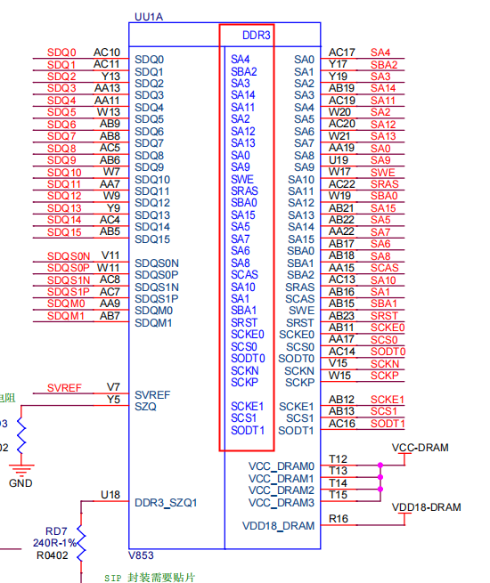
举个其他平台的例子:
这里接的是 LPDDR4,使用LPDDR4的REMAP
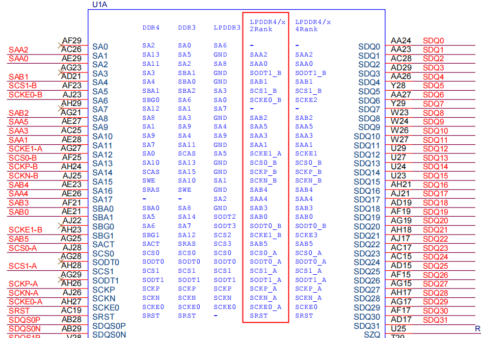
这里接的是DDR4,使用DDR4的REMAP
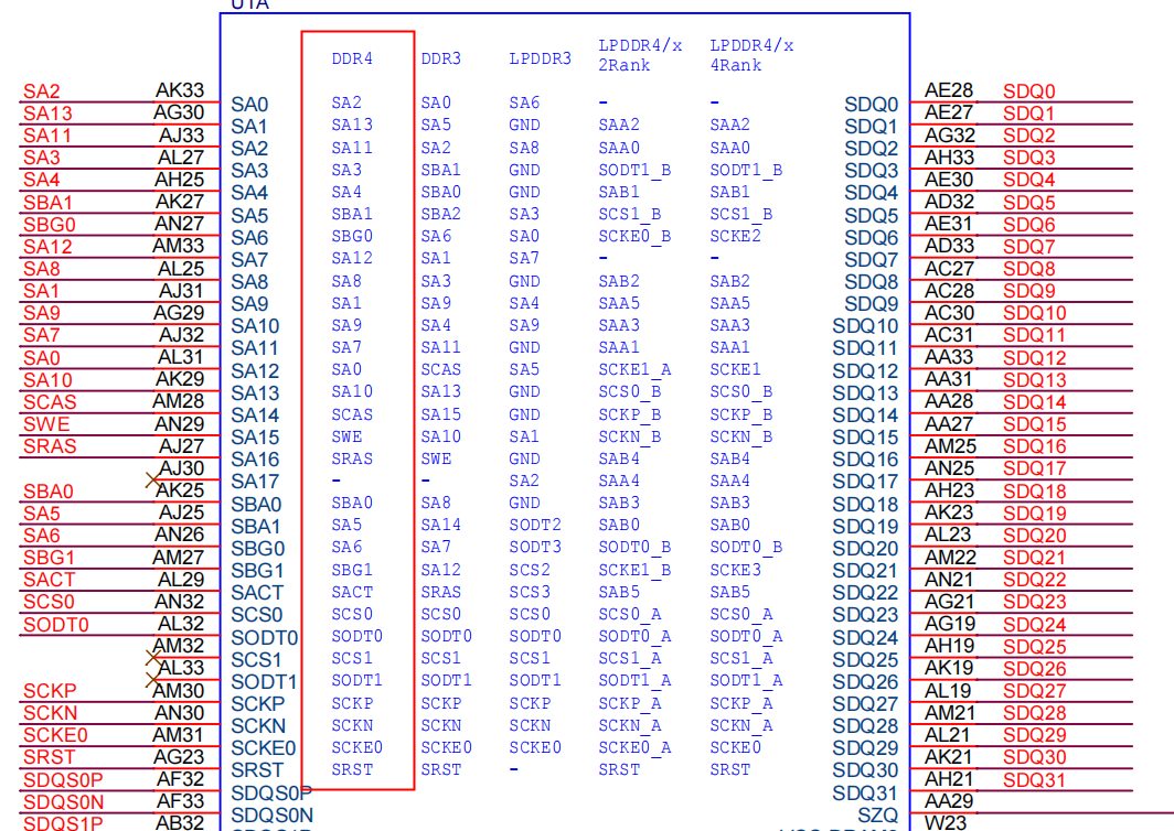
-
回复: 求助 r128 dsp发布在 A Series
RI-2020.5-linux 编译器需要向购买开发板的商家/代理提交申请,需要提供自己的HIFI5 DSP Xtensa Xplorer的证明
-
回复: V851S SPI2 死机发布在 V Series
对照手册:
-
SPI2 地址 0x04027000, 没问题
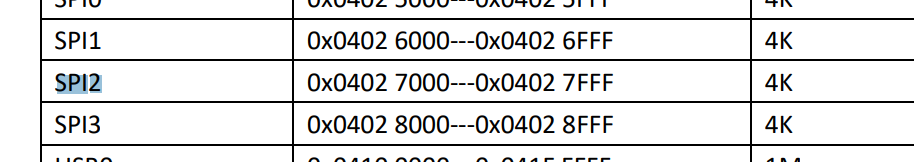
-
SPI2 中断号 49,配置时需要减掉SIG和PPI的数量32,也就是17
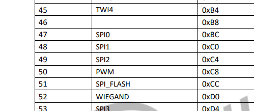
中断号配置错误,应该为17不是18
spi2: spi@04027000 { #address-cells = <1>; #size-cells = <0>; compatible = "allwinner,sun8i-spi"; device_type = "spi2"; reg = <0x0 0x04027000 0x0 0x1000>; interrupts = <GIC_SPI 17 IRQ_TYPE_LEVEL_HIGH>; clocks = <&clk_pll_periph0300m>, <&clk_spi2>; status = "disabled"; }; -
-
回复: V853使用MIPI CSI接口是否只支持RAW格式像素?发布在 V Series
@xjy_5 一般来说配置sensor0_isp_used = <0>; 就不会调用ISP,虽然会配置但是不会处理。需要再跟踪一下调用
-
回复: T113S3双路 dual lvds驱动不起来发布在 T Series
uboot和dtsi里面添加dual link IO的配置
demo:

lvds2link_pins_a: lvds2link@0 {
     allwinner,pins = "PD0", "PD1", "PD2", "PD3", "PD4", "PD5", "PD8", "PD9", "PD6", "PD7", \
     "PD10", "PD11", "PD12", "PD13", "PD14", "PD15", "PD18", "PD19", "PD16", "PD17";
     allwinner,pname = "PD0", "PD1", "PD2", "PD3", "PD4", "PD5", "PD8", "PD9", "PD6", "PD7", \
     "PD10", "PD11", "PD12", "PD13", "PD14", "PD15", "PD18", "PD19", "PD16", "PD17";
     allwinner,function = "lvds1";
     allwinner,muxsel = <3>;
     allwinner,drive = <3>;
     allwinner,pull = <0>;
 };

lvds2link_pins_b: lvds2link@1 {
     allwinner,pins = "PD0", "PD1", "PD2", "PD3", "PD4", "PD5", "PD8", "PD9", "PD6", "PD7", \
     "PD10", "PD11", "PD12", "PD13", "PD14", "PD15", "PD18", "PD19", "PD16", "PD17";
     allwinner,pname = "PD0", "PD1", "PD2", "PD3", "PD4", "PD5", "PD8", "PD9", "PD6", "PD7", \
     "PD10", "PD11", "PD12", "PD13", "PD14", "PD15", "PD18", "PD19", "PD16", "PD17";
     allwinner,function = "lvds1_suspend";
     allwinner,muxsel = <7>;
     allwinner,drive = <3>;
     allwinner,pull = <0>;
 };
dts中 修改为lvds dual link模式,并引用dtsi里配好的dual link IO
&lcd0{
...
 lcd_lvds_if          = <1>;
...
...
pinctrl-0 = <&lvds2link_pins_a>;
pinctrl-1 = <&lvds2link_pins_b>;
...
}
其他和single link的配置方法无异,如果点不亮请检查时序
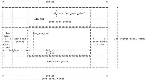
这里看到dclk配置是80
但是手册需求的是54

这里提供一套1920x720的时序作为参考
&lcd0 { lcd_used = <1>; lcd_driver_name = "default_lcd"; lcd_backlight = <50>; lcd_if = <3>; lcd_x = <1920>; lcd_y = <720>; lcd_width = <150>; lcd_height = <94>; lcd_dclk_freq = <94>; lcd_pwm_used = <1>; lcd_pwm_ch = <3>; lcd_pwm_freq = <50000>; lcd_pwm_pol = <1>; lcd_pwm_max_limit = <255>; lcd_hbp = <64>; lcd_ht = <2064>; lcd_hspw = <20>; lcd_vbp = <30>; lcd_vt = <760>; lcd_vspw = <10>; lcd_lvds_if = <1>; lcd_lvds_colordepth = <0>; lcd_lvds_mode = <0>; lcd_frm = <1>; lcd_hv_clk_phase = <0>; lcd_hv_sync_polarity= <0>; lcd_gamma_en = <0>; lcd_bright_curve_en = <0>; lcd_cmap_en = <0>; deu_mode = <0>; lcdgamma4iep = <22>; smart_color = <90>; pinctrl-0 = <&lvds2link_pins_a>; pinctrl-1 = <&lvds2link_pins_b>; }; -
回复: V853 SDK : PMU TWI发布在 V Series
@alb702 在 V853 SDK : PMU TWI 中说:
[267]ic cant match axp, please check...
V853 和 V853s 的芯片安全系统验证不一样,SDK不能通用,这行输出表示芯片型号验证失败,跳过初始化DRAM
-
回复: 测试编译不过发布在 V Series
-
helloworld_fel 使用了 VFP 寄存器参数,但是某个库文件(libgcc.a(_udivmoddi4.o))却不支持。
-
缺少 .note.GNU-stack 段,暗示可执行栈缺失。
-
对于具有 RWX 权限的 LOAD 段,给出了警告。
-
在链接时,出现了对 raise 函数的未定义引用。
-
-
回复: v853 vin通路配置发布在 V Series
(1)在线模式:四个vipp和dma实体,最大缩小比例为16*16,每路最多可支持16个orl
(2)离线模式:每个vipp和dma可分时复用为4个vipp和dma虚拟体,四个vipp和dma实体相互独立,在线模式和离线模式开关也是相互独立的;
(3)VIPP和DAM的分时复用(离线模式)与isp和tdm的分时复用(离线模式)是绑定关系,即tdm和isp开启了离线模式,vipp和dma的输入端如果是isp,那么vipp和dma也需要开启离线模式;
(4)只有VIPP0和dma0实体支持VE在线编码,而vipp0在线,如果vipp00的输入端为isp,那么tdm和isp也只能配置在线模式,而isp在线,那么四个vipp和dma实体都只能配置在线模式;online 和 offline 配 置 方 式 在 board.dts , 所 以 需 要 在 对 应 版 型 的 board.dts 中 找 到 vind0 节 点 配 置 列 表 , 对 应 关 系 为 tdm 对 应 节 点 , isp 对 应 isp00 节 点 , vipp 对 应 scaler00 、 scaler10 、 scaler20 和 scaler30 节 点 , dma 对 , 应 vinc00 、 vinc10 、 vinc20 和 vinc30 节 点 。
- 在线模式,单路3输出
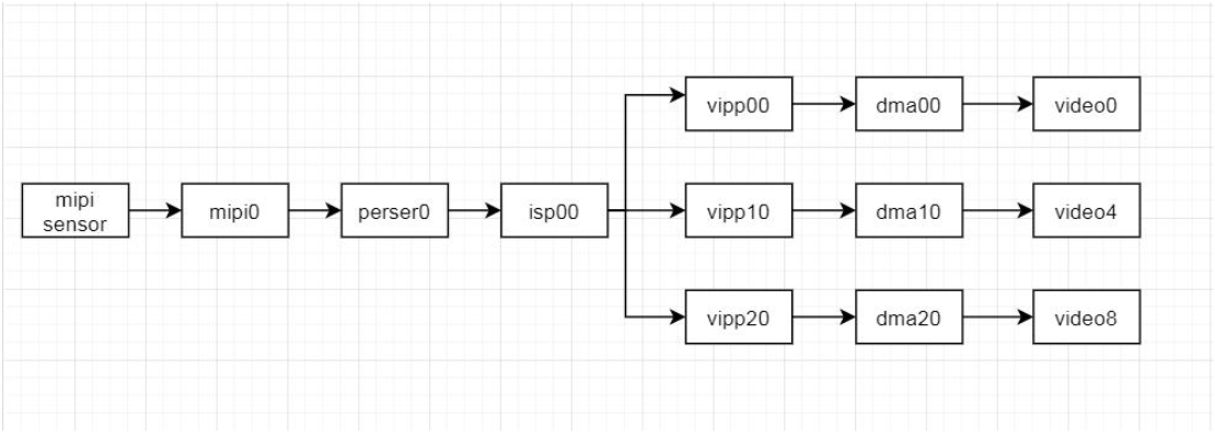
- 离线模式,2路8输出
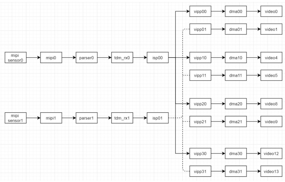
-
T527 使用 DRM 驱动 edp 屏幕发布在 T Series
进入 menuconfig 勾选 drm 驱动
./build.sh menuconfig先勾选 DRM
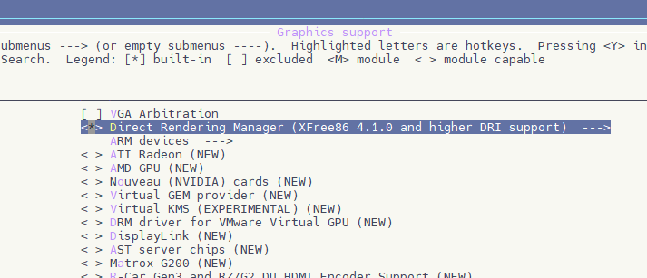
再勾选 DRM 驱动
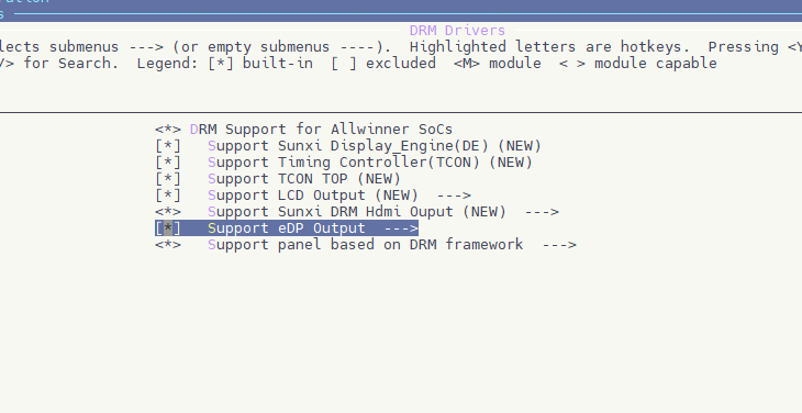
选择驱动的phy
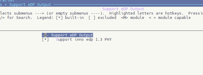
选择屏幕
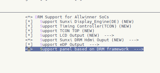
选择 general 屏幕面板驱动
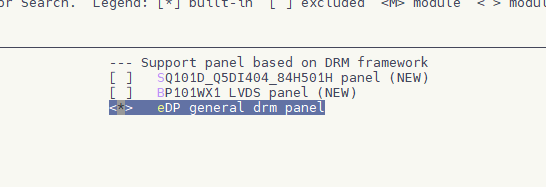
关闭原来的 disp2 fbdev 驱动
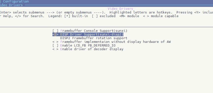
配置设备树
edp_panel_backlight: edp_backlight { compatible = "pwm-backlight"; status = "okay"; brightness-levels = < 0 1 2 3 4 5 6 7 8 9 10 11 12 13 14 15 16 17 18 19 20 21 22 23 24 25 26 27 28 29 30 31 32 33 34 35 36 37 38 39 40 41 42 43 44 45 46 47 48 49 50 51 52 53 54 55 56 57 58 59 60 61 62 63 64 65 66 67 68 69 70 71 72 73 74 75 76 77 78 79 80 81 82 83 84 85 86 87 88 89 90 91 92 93 94 95 96 97 98 99 100 101 102 103 104 105 106 107 108 109 110 111 112 113 114 115 116 117 118 119 120 121 122 123 124 125 126 127 128 129 130 131 132 133 134 135 136 137 138 139 140 141 142 143 144 145 146 147 148 149 150 151 152 153 154 155 156 157 158 159 160 161 162 163 164 165 166 167 168 169 170 171 172 173 174 175 176 177 178 179 180 181 182 183 184 185 186 187 188 189 190 191 192 193 194 195 196 197 198 199 200 201 202 203 204 205 206 207 208 209 210 211 212 213 214 215 216 217 218 219 220 221 222 223 224 225 226 227 228 229 230 231 232 233 234 235 236 237 238 239 240 241 242 243 244 245 246 247 248 249 250 251 252 253 254 255>; default-brightness-level = <200>; enable-gpios = <&pio PI 5 GPIO_ACTIVE_HIGH>; /* power-supply = <®_backlight_12v>; */ pwms = <&a_pwm 5 5000000 0>; }; edp_panel: edp_panel { compatible = "edp-general-panel"; status = "okay"; power0-supply = <®_dcdc4>; backlight = <&edp_panel_backlight>; panel-timing { clock-frequency = <348577920>; /* pixel clock */ hactive = <2560>; hback-porch = <120>; hfront-porch = <88>; hsync-len = <32>; vactive = <1600>; vback-porch = <71>; vfront-porch = <28>; vsync-len = <5>; /* hor_sync_polarity */ hsync-active = <1>; /* ver_sync_polarity */ vsync-active = <1>; // unused now /* de-active = <1>; pixelclk-active = <1>; syncclk-active = <0>; interlaced; doublescan; doubleclk; */ }; ports { #address-cells = <1>; #size-cells = <0>; panel_in: port@0 { #address-cells = <1>; #size-cells = <0>; reg = <0>; edp_panel_in: endpoint@0 { reg = <0>; remote-endpoint = <&edp_panel_out>; }; }; }; };和 drm_edp 的配置
&drm_edp { status = "okay"; edp_ssc_en = <0>; edp_ssc_mode = <0>; edp_psr_support = <0>; edp_colordepth = <8>; /* 6/8/10/12/16 */ edp_color_fmt = <0>; /* 0:RGB 1: YUV444 2: YUV422 */ lane1_sw = <0>; lane1_pre = <0>; lane2_sw = <0>; lane2_pre = <0>; lane3_sw = <0>; lane3_pre = <0>; efficient_training = <0>; sink_capacity_prefer = <1>; edid_timings_prefer = <1>; timings_fixed = <1>; vcc-edp-supply = <®_bldo3>; vdd-edp-supply = <®_dcdc2>; panel = <&edp_panel>; ports { edp_out: port@1 { edp_panel_out: endpoint@0 { reg = <0>; remote-endpoint = <&edp_panel_in>; }; }; }; }; -
回复: V851S tina linux ov5647 驱动程序没有 dmesg发布在 V Series
使用 V3s SDK 提供VFE框架的驱动移植到VIN框架下抓图成功。但是图像非常暗,并且撕裂,抓raw数据查看也是一样,考虑可能mclk不同步导致。
sensor0:sensor@0 {
	device_type = "sensor0";
	sensor0_mname = "ov5648_mipi";
	sensor0_twi_cci_id = <0>;
	sensor0_twi_addr = <0x6c>;
	sensor0_mclk_id = <0>;
	sensor0_pos = "rear";
	sensor0_isp_used = <1>;
	sensor0_fmt = <1>;
	sensor0_stby_mode = <0>;
	sensor0_vflip = <0>;
	sensor0_hflip = <0>;
	sensor0_iovdd-supply = <>;
	sensor0_iovdd_vol = <1800000>;
	sensor0_avdd-supply = <>;
	sensor0_avdd_vol = <2800000>;
	sensor0_dvdd-supply = <>;
	sensor0_dvdd_vol = <1200000>;
	sensor0_power_en = <>;
	sensor0_reset = <&pio PA 18 1 0 1 0>;
	sensor0_pwdn = <&pio PA 19 1 0 1 0>;
	sensor0_sm_hs = <>;
	sensor0_sm_vs = <>;
	flash_handle = <>;
	act_handle = <>;
	status	= "okay";
};
/* * A V4L2 driver for ov5647 Raw cameras. * * Copyright (c) 2022 by YuzukiTsuru <gloomyghost@gloomyghost.com> * Copyright (c) 2018 by Allwinnertech Co., Ltd. http://www.allwinnertech.com * * Authors: Zheng ZeQun <zequnzheng@allwinnertech.com> * Liang WeiJie <liangweijie@allwinnertech.com> * YuzukiTsuru <gloomyghost@gloomyghost.com> * * This program is free software; you can redistribute it and/or modify * it under the terms of the GNU General Public License version 2 as * published by the Free Software Foundation. */ #include <linux/init.h> #include <linux/module.h> #include <linux/slab.h> #include <linux/i2c.h> #include <linux/delay.h> #include <linux/videodev2.h> #include <linux/clk.h> #include <media/v4l2-device.h> #include <media/v4l2-mediabus.h> #include <linux/io.h> #include "camera.h" #include "sensor_helper.h" MODULE_AUTHOR("YuzukiTsuru"); MODULE_DESCRIPTION("A low-level driver for ov5647 sensors"); MODULE_LICENSE("GPL"); #define MCLK (24*1000*1000) #define V4L2_IDENT_SENSOR 0x5648 /* * Our nominal (default) frame rate. */ #define SENSOR_FRAME_RATE 30 /* * The GC0310 i2c address */ #define I2C_ADDR 0x6c #define SENSOR_NAME "ov5648_mipi" /* * The default register settings */ static struct regval_list sensor_default_regs[] = { //Slave_ID=0x6c; {0x0100, 0x00},// ; software standby {0x0103, 0x01},// ; software reset {REG_DLY, 0x25}, {0x370c, 0x03},// ; analog control {0x5000, 0x06},// ; lens off, bpc on, wpc on {0x5003, 0x08},// ; buf_en {0x5a00, 0x08},// {0x3000, 0xff},// ; D[9:8] output {0x3001, 0xff},// ; D[7:0] output {0x3002, 0xff},// ; Vsync, Href, PCLK, Frex, Strobe, SDA, GPIO1, GPIO0 output {0x301d, 0xf0},// {0x3a18, 0x00},// ; gain ceiling = 15.5x {0x3a19, 0xf8},// ; gain ceiling {0x3c01, 0x80},// ; band detection manual mode {0x3b07, 0x0c},// ; strobe frex mode //; analog control {0x3630, 0x2e}, {0x3632, 0xe2}, {0x3633, 0x23}, {0x3634, 0x44}, {0x3620, 0x64}, {0x3621, 0xe0}, {0x3600, 0x37}, {0x3704, 0xa0}, {0x3703, 0x5a}, {0x3715, 0x78}, {0x3717, 0x01}, {0x3731, 0x02}, {0x370b, 0x60}, {0x3705, 0x1a}, {0x3f05, 0x02}, {0x3f06, 0x10}, {0x3f01, 0x0a}, //; AG/AE target {0x3a0f, 0x58},// ; stable in high {0x3a10, 0x50},// ; stable in low {0x3a1b, 0x58},// ; stable out high {0x3a1e, 0x50},// ; stable out low {0x3a11, 0x60},// ; fast zone high {0x3a1f, 0x28},// ; fast zone low {0x4001, 0x02},// ; BLC start line {0x4000, 0x09},// ; BLC enable {0x3000, 0x00},// ; D[9:8] input {0x3001, 0x00},// ; D[7:0] input {0x3002, 0x00},// ; Vsync, Href, PCLK, Frex, Strobe, SDA, GPIO1, GPIO0 input {0x3017, 0xe0},// ; MIPI PHY {0x301c, 0xfc},// {0x3636, 0x06},// ; analog control {0x3016, 0x08},// ; MIPI pad enable {0x3827, 0xec},// {0x3018, 0x44},// ; MIPI 2 lane, MIPI enable {0x3035, 0x21},// ; PLL {0x3106, 0xf5},// ; PLL {0x3034, 0x1a},// ; PLL {0x301c, 0xf8},// {0x3503, 0x03},// ; Gain has no latch delay, AGC manual, AEC {0x3501, 0x10},// ; exposure[15:8] {0x3502, 0x80},// ; exposure[7:0] {0x350a, 0x00},// ; gain[9:8] {0x350b, 0x7f},// ; gain[7:0] {0x5001, 0x01},// ; AWB on {0x5180, 0x08},// ; AWB manual gain enable {0x5186, 0x04},// ; manual red gain high {0x5187, 0x00},// ; manual red gain low {0x5188, 0x04},// ; manual green gain high {0x5189, 0x00},// ; manual green gain low {0x518a, 0x04},// ; manual blue gain high {0x518b, 0x00},// ; manual blue gain low {0x5000, 0x06},// ; lenc off, bpc on, wpc on }; static struct regval_list sensor_qsxga_regs[] = { //qsxga: 2592*1936@15fps {0x0100, 0x00},// ; software standby {0x3035, 0x21},// ; PLL {0x3036, 0x66},// ; PLL {0x303c, 0x11},// ; PLL {0x3821, 0x06},// ; ISP mirror on, Sensor mirror on {0x3820, 0x00},// ; ISP flip off, Sensor flip off {0x3612, 0x5b},// ; analog control {0x3618, 0x04},// ; analog control {0x380c, 0x0a},// ; HTS = 2752 {0x380d, 0xc0},// ; HTS {0x380e, 0x07},// ; VTS = 1974 {0x380f, 0xb6},// ; VTS {0x3814, 0x11},// ; X INC {0x3815, 0x11},// ; X INC {0x3708, 0x64},// ; analog control {0x3709, 0x12},// ; analog control {0x3808, 0x0a},// ; X OUTPUT SIZE = 2592 {0x3809, 0x20},// ; X OUTPUT SIZE {0x380a, 0x07},// ; Y OUTPUT SIZE = 1944 {0x380b, 0x98},// ; Y OUTPUT SIZE {0x3800, 0x00},// ; X Start {0x3801, 0x0c},// ; X Start {0x3802, 0x00},// ; Y Start {0x3803, 0x02},// ; Y Start {0x3804, 0x0a},// ; X End {0x3805, 0x33},// ; X End {0x3806, 0x07},// ; Y End {0x3807, 0xa1},// ; Y End ///////////; Banding filter {0x3a08, 0x01},// ; B50 {0x3a09, 0x28},// ; B50 {0x3a0a, 0x00},// ; B60 {0x3a0b, 0xf6},// ; B60 {0x3a0d, 0x07},// ; B60 max {0x3a0e, 0x06},// ; B50 max {0x4004, 0x04},// ; black line number {0x4837, 0x19},// ; MIPI pclk period {0x0100, 0x01},// ; wake up from software standby }; static struct regval_list sensor_720p_regs[] = { //720: 1280*720@30fps {0x0100, 0x00},// ; software standby {0x3035, 0x21},// ; PLL {0x3036, 0x46},// ; PLL {0x303c, 0x11},// ; PLL {0x3821, 0x07},// ; ISP mirror on, Sensor mirror on, bin on {0x3820, 0x41},// ; ISP flip off, Sensor flip off, bin on {0x3612, 0x59},// ; analog control {0x3618, 0x00},// ; analog control {0x380c, 0x07},// ; HTS = 1896 {0x380d, 0x68},// ; HTS {0x380e, 0x03},// ; VTS = 984 {0x380f, 0xd8},// ; VTS {0x3814, 0x31},// ; X INC {0x3815, 0x31},// ; Y INC {0x3708, 0x64},// ; analog control {0x3709, 0x52},// ; analog control {0x3808, 0x05},// ; X OUTPUT SIZE = 1280 {0x3809, 0x00},// ; X OUTPUT SIZE {0x380a, 0x03},// ; Y OUTPUT SIZE = 960 {0x380b, 0xc0},// ; Y OUTPUT SIZE {0x3800, 0x00},// ; X Start {0x3801, 0x18},// ; X Start {0x3802, 0x00},// ; Y Start {0x3803, 0x0e},// ; Y Start {0x3804, 0x0a},// ; X End {0x3805, 0x27},// ; X End {0x3806, 0x07},// ; Y End {0x3807, 0x95},// ; Y End // banding filter {0x3a08, 0x01},// ; B50 {0x3a09, 0x27},// ; B50 {0x3a0a, 0x00},// ; B60 {0x3a0b, 0xf6},// ; B60 {0x3a0d, 0x04},// ; B50 max {0x3a0e, 0x03},// ; B60 max {0x4004, 0x02},// ; black line number {0x4837, 0x24},// ; MIPI pclk period {0x0100, 0x01},// ; wake up from software standby }; static struct regval_list sensor_fmt_raw[] = { }; /* * Code for dealing with controls. * fill with different sensor module * different sensor module has different settings here * if not support the follow function ,retrun -EINVAL */ static int sensor_g_exp(struct v4l2_subdev *sd, __s32 *value) { struct sensor_info *info = to_state(sd); *value = info->exp; sensor_print("sensor_get_exposure = %d\n", info->exp); return 0; } static int sensor_s_exp(struct v4l2_subdev *sd, unsigned int exp_val) { unsigned char explow, expmid, exphigh; struct sensor_info *info = to_state(sd); if(exp_val>0xfffff) exp_val=0xfffff; sensor_write(sd, 0x3208, 0x00);//enter group write sensor_write(sd, 0x3503, 0x13); exphigh = (unsigned char) ( (0x0f0000&exp_val)>>16); expmid = (unsigned char) ( (0x00ff00&exp_val)>>8); explow = (unsigned char) ( (0x0000ff&exp_val) ); //sensor_write(sd, 0x3208, 0x00);//enter group write sensor_write(sd, 0x3502, explow); sensor_write(sd, 0x3501, expmid); sensor_write(sd, 0x3500, exphigh); sensor_write(sd, 0x3208, 0x10);//end group write sensor_write(sd, 0x3208, 0xa0);//init group write sensor_print("ov5647_mipi sensor_set_exp = %d, Done!\n", exp_val); info->exp = exp_val; return 0; } static int sensor_g_gain(struct v4l2_subdev *sd, __s32 *value) { struct sensor_info *info = to_state(sd); *value = info->gain; sensor_print("sensor_get_gain = %d\n", info->gain); return 0; } static int sensor_s_gain(struct v4l2_subdev *sd, unsigned int gain_val) { struct sensor_info *info = to_state(sd); unsigned char gainlow=0; unsigned char gainhigh=0; if(gain_val<1*16) gain_val=16; if(gain_val>64*16-1) gain_val=64*16-1; gainlow=(unsigned char)(gain_val&0xff); gainhigh=(unsigned char)((gain_val>>8)&0x3); sensor_write(sd, 0x3208, 0x00);//enter group write sensor_write(sd, 0x3503, 0x13); sensor_write(sd, 0x350b, gainlow); sensor_write(sd, 0x350a, gainhigh); sensor_write(sd, 0x3208, 0x10);//end group write sensor_write(sd, 0x3208, 0xa0);//init group write //printk("ov5647_mipi sensor_set_gain = %d, Done!\n", gain_val); info->gain = gain_val; return 0; } static int ov5648_sensor_vts; static int sensor_s_exp_gain(struct v4l2_subdev *sd, struct sensor_exp_gain *exp_gain) { int exp_val, gain_val,frame_length,shutter; unsigned char explow=0,expmid=0,exphigh=0; unsigned char gainlow=0,gainhigh=0; struct sensor_info *info = to_state(sd); exp_val = exp_gain->exp_val; gain_val = exp_gain->gain_val; if(gain_val<1*16) gain_val=16; if(gain_val>64*16-1) gain_val=64*16-1; if(exp_val>0xfffff) exp_val=0xfffff; gainlow=(unsigned char)(gain_val&0xff); gainhigh=(unsigned char)((gain_val>>8)&0x3); exphigh = (unsigned char) ( (0x0f0000&exp_val)>>16); expmid = (unsigned char) ( (0x00ff00&exp_val)>>8); explow = (unsigned char) ( (0x0000ff&exp_val) ); shutter = exp_val/16; sensor_print("ov5648_sensor_vts = %d\n",ov5648_sensor_vts); if(shutter > ov5648_sensor_vts- 4) frame_length = shutter + 4; else frame_length = ov5648_sensor_vts; sensor_write(sd, 0x3503, 0x07); sensor_write(sd, 0x380f, (frame_length & 0xff)); sensor_write(sd, 0x380e, (frame_length >> 8)); sensor_print("exp_val = %d,gain_val = %d\n",exp_val,gain_val); sensor_write(sd, 0x3208, 0x00);//enter group write sensor_write(sd, 0x350b, gainlow); sensor_write(sd, 0x350a, gainhigh); sensor_write(sd, 0x3502, explow); sensor_write(sd, 0x3501, expmid); sensor_write(sd, 0x3500, exphigh); sensor_write(sd, 0x3208, 0x10);//end group write sensor_write(sd, 0x3208, 0xa0);//init group write info->exp = exp_val; info->gain = gain_val; return 0; } static void sensor_s_sw_stby(struct v4l2_subdev *sd, int on_off) { int ret = 0; return ret; } /* * Stuff that knows about the sensor. */ static int sensor_power(struct v4l2_subdev *sd, int on) { int ret = 0; sensor_print("ov5648 sensor_power\n"); switch (on) { case STBY_ON: sensor_print("STBY_ON!\n"); cci_lock(sd); sensor_s_sw_stby(sd, STBY_ON); usleep_range(1000, 1200); cci_unlock(sd); break; case STBY_OFF: sensor_print("STBY_OFF!\n"); cci_lock(sd); usleep_range(1000, 1200); sensor_s_sw_stby(sd, STBY_OFF); cci_unlock(sd); break; case PWR_ON: sensor_print("PWR_ON!100\n"); cci_lock(sd); vin_gpio_set_status(sd, PWDN, 1); vin_gpio_write(sd, RESET, CSI_GPIO_HIGH); vin_gpio_set_status(sd, POWER_EN, 1); vin_gpio_write(sd, PWDN, CSI_GPIO_LOW); vin_gpio_write(sd, RESET, CSI_GPIO_LOW); vin_gpio_write(sd, POWER_EN, CSI_GPIO_HIGH); usleep_range(7000, 8000); vin_set_pmu_channel(sd, IOVDD, ON); usleep_range(7000, 8000); vin_set_pmu_channel(sd, AVDD, ON); vin_set_pmu_channel(sd, AFVDD, ON); usleep_range(7000, 8000); vin_set_pmu_channel(sd, DVDD, ON); usleep_range(7000, 8000); vin_set_mclk_freq(sd, MCLK); vin_set_mclk(sd, ON); usleep_range(10000, 12000); vin_gpio_write(sd, RESET, CSI_GPIO_HIGH); vin_gpio_write(sd, PWDN, CSI_GPIO_HIGH); vin_set_pmu_channel(sd, CAMERAVDD, ON);/*AFVCC ON*/ usleep_range(10000, 12000); cci_unlock(sd); break; case PWR_OFF: sensor_print("PWR_OFF!\n"); cci_lock(sd); vin_gpio_write(sd, PWDN, CSI_GPIO_HIGH); vin_gpio_write(sd, RESET, CSI_GPIO_HIGH); vin_set_mclk(sd, OFF); usleep_range(7000, 8000); vin_set_pmu_channel(sd, DVDD, OFF); vin_gpio_write(sd, PWDN, CSI_GPIO_LOW); vin_gpio_write(sd, RESET, CSI_GPIO_LOW); vin_gpio_write(sd, POWER_EN, CSI_GPIO_LOW); vin_set_pmu_channel(sd, AVDD, OFF); vin_set_pmu_channel(sd, IOVDD, OFF); vin_set_pmu_channel(sd, AFVDD, OFF); vin_set_pmu_channel(sd, CAMERAVDD, OFF);/*AFVCC ON*/ cci_unlock(sd); break; default: return -EINVAL; } return 0; } static int sensor_reset(struct v4l2_subdev *sd, u32 val) { switch (val) { case 0: vin_gpio_write(sd, RESET, CSI_GPIO_HIGH); usleep_range(10000,12000); break; case 1: vin_gpio_write(sd, RESET, CSI_GPIO_LOW); usleep_range(10000,12000); break; default: return -EINVAL; } return 0; } static int sensor_detect(struct v4l2_subdev *sd) { data_type rdval; unsigned int SENSOR_ID = 0; sensor_read(sd, 0x300A, &rdval); SENSOR_ID |= rdval; SENSOR_ID |= (rdval << 8); sensor_read(sd, 0x300B, &rdval); SENSOR_ID |= (rdval); sensor_print("V4L2_IDENT_SENSOR = 0x%x\n", SENSOR_ID); if (SENSOR_ID != V4L2_IDENT_SENSOR) { sensor_print("ov5648 %s error, chip found is not an target chip", __func__); //return -ENODEV; } return 0; } static int sensor_init(struct v4l2_subdev *sd, u32 val) { int ret; struct sensor_info *info = to_state(sd); sensor_print("sensor_init\n"); /*Make sure it is a target sensor */ ret = sensor_detect(sd); if (ret) { sensor_err("chip found is not an target chip.\n"); return ret; } info->focus_status = 0; info->low_speed = 0; info->width = QSXGA_WIDTH; info->height = QSXGA_HEIGHT; info->hflip = 0; info->vflip = 0; info->gain = 0; info->tpf.numerator = 1; info->tpf.denominator = 30; /* 30fps */ info->preview_first_flag = 1; return 0; } static long sensor_ioctl(struct v4l2_subdev *sd, unsigned int cmd, void *arg) { int ret = 0; struct sensor_info *info = to_state(sd); switch (cmd) { case GET_CURRENT_WIN_CFG: if (info->current_wins != NULL) { memcpy(arg, info->current_wins, sizeof(struct sensor_win_size)); ret = 0; } else { sensor_err("empty wins!\n"); ret = -1; } break; case SET_FPS: ret = 0; break; case VIDIOC_VIN_SENSOR_EXP_GAIN: ret = sensor_s_exp_gain(sd, (struct sensor_exp_gain *)arg); break; case VIDIOC_VIN_SENSOR_CFG_REQ: sensor_cfg_req(sd, (struct sensor_config *)arg); break; case VIDIOC_VIN_ACT_INIT: ret = actuator_init(sd, (struct actuator_para *)arg); break; case VIDIOC_VIN_ACT_SET_CODE: ret = actuator_set_code(sd, (struct actuator_ctrl *)arg); break; default: return -EINVAL; } return ret; } /* * Store information about the video data format. */ static struct sensor_format_struct sensor_formats[] = { { .desc = "Raw RGB Bayer", .mbus_code = MEDIA_BUS_FMT_SBGGR10_1X10, .regs = sensor_fmt_raw, .regs_size = ARRAY_SIZE(sensor_fmt_raw), .bpp = 1 }, }; #define N_FMTS ARRAY_SIZE(sensor_formats) /* * Then there is the issue of window sizes. Try to capture the info here. */ static struct sensor_win_size sensor_win_sizes[] = { { .width = QSXGA_WIDTH, .height = QSXGA_HEIGHT, .hoffset = 0, .voffset = 4, .hts = 2752, .vts = 1974, .pclk = 81486720, .mipi_bps = 408*1000*1000, .fps_fixed = 2, .bin_factor = 1, .intg_min = 1, .intg_max = (1974)<<4, .gain_min = 1<<4, .gain_max = 12<<4, .regs = sensor_qsxga_regs, .regs_size = ARRAY_SIZE(sensor_qsxga_regs), .set_size = NULL, }, { .width = HD720_WIDTH, .height = HD720_HEIGHT, .hoffset = 0, .voffset = 120, .hts = 1896, .vts = 984, .pclk = 56*1000*1000, .mipi_bps = 280*1000*1000, .fps_fixed = 1, .bin_factor = 1, .intg_min = 1, .intg_max = 984<<4, .gain_min = 1<<4, .gain_max = 12<<4, .regs = sensor_720p_regs,// .regs_size = ARRAY_SIZE(sensor_720p_regs),// .set_size = NULL, }, }; #define N_WIN_SIZES (ARRAY_SIZE(sensor_win_sizes)) static int sensor_reg_init(struct sensor_info *info) { int ret; struct v4l2_subdev *sd = &info->sd; struct sensor_format_struct *sensor_fmt = info->fmt; struct sensor_win_size *wsize = info->current_wins; ret = sensor_write_array(sd, sensor_default_regs, ARRAY_SIZE(sensor_default_regs)); if (ret < 0) { sensor_err("write sensor_default_regs error\n"); return ret; } sensor_print("sensor_reg_init\n"); sensor_write_array(sd, sensor_fmt->regs, sensor_fmt->regs_size); if (wsize->regs) sensor_write_array(sd, wsize->regs, wsize->regs_size); if (wsize->set_size) wsize->set_size(sd); info->width = wsize->width; info->height = wsize->height; info->exp = 0; info->gain = 0; ov5648_sensor_vts = wsize->vts; sensor_print("s_fmt set width = %d, height = %d\n", wsize->width, wsize->height); return 0; } static int sensor_s_stream(struct v4l2_subdev *sd, int enable) { struct sensor_info *info = to_state(sd); sensor_print("%s on = %d, %d*%d fps: %d code: %x\n", __func__, enable, info->current_wins->width, info->current_wins->height, info->current_wins->fps_fixed, info->fmt->mbus_code); if (!enable) return 0; return sensor_reg_init(info); } static int sensor_g_mbus_config(struct v4l2_subdev *sd, struct v4l2_mbus_config *cfg) { cfg->type = V4L2_MBUS_CSI2; cfg->flags = 0 | V4L2_MBUS_CSI2_2_LANE | V4L2_MBUS_CSI2_CHANNEL_0; return 0; } static int sensor_g_ctrl(struct v4l2_ctrl *ctrl) { struct sensor_info *info = container_of(ctrl->handler, struct sensor_info, handler); struct v4l2_subdev *sd = &info->sd; switch (ctrl->id) { case V4L2_CID_GAIN: return sensor_g_gain(sd, &ctrl->val); case V4L2_CID_EXPOSURE: return sensor_g_exp(sd, &ctrl->val); } return -EINVAL; } static int sensor_s_ctrl(struct v4l2_ctrl *ctrl) { struct sensor_info *info = container_of(ctrl->handler, struct sensor_info, handler); struct v4l2_subdev *sd = &info->sd; switch (ctrl->id) { case V4L2_CID_GAIN: return sensor_s_gain(sd, ctrl->val); case V4L2_CID_EXPOSURE: return sensor_s_exp(sd, ctrl->val); } return -EINVAL; } /* ----------------------------------------------------------------------- */ static const struct v4l2_ctrl_ops sensor_ctrl_ops = { .g_volatile_ctrl = sensor_g_ctrl, .s_ctrl = sensor_s_ctrl, }; static const struct v4l2_subdev_core_ops sensor_core_ops = { .reset = sensor_reset, .init = sensor_init, .s_power = sensor_power, .ioctl = sensor_ioctl, #ifdef CONFIG_COMPAT .compat_ioctl32 = sensor_compat_ioctl32, #endif }; static const struct v4l2_subdev_video_ops sensor_video_ops = { .s_parm = sensor_s_parm, .g_parm = sensor_g_parm, .s_stream = sensor_s_stream, .g_mbus_config = sensor_g_mbus_config, }; static const struct v4l2_subdev_pad_ops sensor_pad_ops = { .enum_mbus_code = sensor_enum_mbus_code, .enum_frame_size = sensor_enum_frame_size, .get_fmt = sensor_get_fmt, .set_fmt = sensor_set_fmt, }; static const struct v4l2_subdev_ops sensor_ops = { .core = &sensor_core_ops, .video = &sensor_video_ops, .pad = &sensor_pad_ops, }; /* ----------------------------------------------------------------------- */ static struct cci_driver cci_drv = { .name = SENSOR_NAME, .addr_width = CCI_BITS_16, .data_width = CCI_BITS_8, }; static const struct v4l2_ctrl_config sensor_custom_ctrls[] = { { .ops = &sensor_ctrl_ops, .id = V4L2_CID_FRAME_RATE, .name = "frame rate", .type = V4L2_CTRL_TYPE_INTEGER, .min = 15, .max = 120, .step = 1, .def = 120, }, }; static int sensor_init_controls(struct v4l2_subdev *sd, const struct v4l2_ctrl_ops *ops) { struct sensor_info *info = to_state(sd); struct v4l2_ctrl_handler *handler = &info->handler; struct v4l2_ctrl *ctrl; int i; int ret = 0; v4l2_ctrl_handler_init(handler, 2 + ARRAY_SIZE(sensor_custom_ctrls)); v4l2_ctrl_new_std(handler, ops, V4L2_CID_GAIN, 1 * 1600, 256 * 1600, 1, 1 * 1600); ctrl = v4l2_ctrl_new_std(handler, ops, V4L2_CID_EXPOSURE, 0, 65536 * 16, 1, 0); if (ctrl != NULL) ctrl->flags |= V4L2_CTRL_FLAG_VOLATILE; for (i = 0; i < ARRAY_SIZE(sensor_custom_ctrls); i++) v4l2_ctrl_new_custom(handler, &sensor_custom_ctrls[i], NULL); if (handler->error) { ret = handler->error; v4l2_ctrl_handler_free(handler); } sd->ctrl_handler = handler; return ret; } static int sensor_probe(struct i2c_client *client, const struct i2c_device_id *id) { struct v4l2_subdev *sd; struct sensor_info *info; info = kzalloc(sizeof(struct sensor_info), GFP_KERNEL); if (info == NULL) return -ENOMEM; sd = &info->sd; cci_dev_probe_helper(sd, client, &sensor_ops, &cci_drv); sensor_init_controls(sd, &sensor_ctrl_ops); mutex_init(&info->lock); #ifdef CONFIG_SAME_I2C info->sensor_i2c_addr = I2C_ADDR >> 1; #endif info->fmt = &sensor_formats[0]; info->fmt_pt = &sensor_formats[0]; info->win_pt = &sensor_win_sizes[0]; info->fmt_num = N_FMTS; info->win_size_num = N_WIN_SIZES; info->sensor_field = V4L2_FIELD_NONE; info->stream_seq = MIPI_BEFORE_SENSOR; info->af_first_flag = 1; info->exp = 0; info->gain = 0; return 0; } static int sensor_remove(struct i2c_client *client) { struct v4l2_subdev *sd; sd = cci_dev_remove_helper(client, &cci_drv); kfree(to_state(sd)); return 0; } static const struct i2c_device_id sensor_id[] = { {SENSOR_NAME, 0}, {} }; MODULE_DEVICE_TABLE(i2c, sensor_id); static struct i2c_driver sensor_driver = { .driver = { .owner = THIS_MODULE, .name = SENSOR_NAME, }, .probe = sensor_probe, .remove = sensor_remove, .id_table = sensor_id, }; static __init int init_sensor(void) { return cci_dev_init_helper(&sensor_driver); } static __exit void exit_sensor(void) { cci_dev_exit_helper(&sensor_driver); } module_init(init_sensor); module_exit(exit_sensor);另外建议使用支持列表中的摄像头,例如gc2053,gc2063,这些摄像头已经适配量产完成并且调整ISP后画质更佳,也支持aiisp实现低照度全彩画质,树莓派的摄像头不推荐使用,因为他是外挂mclk的会引起芯片处于错误的模式,另外原厂也没有相应的支持(2017年前的芯片才有这个支持)
IMX219 同样可以使用,但是请注意4lane的摄像头不可适配2lane的数据
-
回复: V853 和 V853S NPU算力差了0.2,这个0.2在具体应用上会有明显的性能差距吗?主要用来做目标检测,静态场景。发布在 V Series
根据具体的模型和需求的规格来看,实际感觉差不多
-
回复: v821切换到spi nand flash(XT26G01CWSIG) 系统无法启动发布在 V Series
看日志是内核整套ubi都没开起来,可以再次运行quick_config,重新编译SDK测试下
-
回复: V853使用MIPI CSI接口是否只支持RAW格式像素?发布在 V Series
@xjy_5 RGB888_1X24 我感觉是直出RGB信号的吧
这个DTSI是在T507上配置的,可以参考一下
vind0:vind@0 { compatible = "allwinner,sunxi-vin-media", "simple-bus"; #address-cells = <2>; #size-cells = <2>; ranges; device_id = <0>; vind0_clk = <384000000>; reg = <0x0 0x06600800 0x0 0x200>, <0x0 0x06600000 0x0 0x800>; clocks = <&clk_csi_top>, <&clk_pll_csi>, <&clk_csi_master0>, <&clk_hosc>, <&clk_pll_csi>, <&clk_csi_master1>, <&clk_hosc>, <&clk_pll_csi>; pinctrl-names = "mclk0-default","mclk0-sleep","mclk1-default","mclk1-sleep"; pinctrl-0 = <&csi_mclk0_pins_a>; pinctrl-1 = <&csi_mclk0_pins_b>; pinctrl-2 = <&csi_mclk1_pins_a>; pinctrl-3 = <&csi_mclk1_pins_b>; status = "okay"; csi_cci0:cci@0 { compatible = "allwinner,sunxi-csi_cci"; reg = <0x0 0x06614000 0x0 0x400>; interrupts = <GIC_SPI 75 IRQ_TYPE_LEVEL_HIGH>; pinctrl-names = "default","sleep"; pinctrl-0 = <&csi_cci0_pins_a>; pinctrl-1 = <&csi_cci0_pins_b>; device_id = <0>; status = "okay"; }; csi_cci1:cci@1 { compatible = "allwinner,sunxi-csi_cci"; reg = <0x0 0x06614400 0x0 0x400>; interrupts = <GIC_SPI 76 IRQ_TYPE_LEVEL_HIGH>; pinctrl-names = "default","sleep"; pinctrl-0 = <&csi_cci1_pins_a>; pinctrl-1 = <&csi_cci1_pins_b>; device_id = <1>; status = "okay"; }; csi0:csi@0 { device_type = "csi0"; compatible = "allwinner,sunxi-csi"; reg = <0x0 0x06601000 0x0 0x1000>; interrupts = <GIC_SPI 73 IRQ_TYPE_LEVEL_HIGH>; device_id = <0>; iommus = <&mmu_aw 4 1>; status = "okay"; }; csi1:csi@1 { device_type = "csi1"; compatible = "allwinner,sunxi-csi"; reg = <0x0 0x06602000 0x0 0x1000>; interrupts = <GIC_SPI 74 IRQ_TYPE_LEVEL_HIGH>; pinctrl-names = "default","sleep"; pinctrl-0 = <&csi1_pins_a>; pinctrl-1 = <&csi1_pins_b>; device_id = <1>; iommus = <&mmu_aw 4 1>; status = "okay"; }; mipi0:mipi@0 { compatible = "allwinner,sunxi-mipi"; reg = <0x0 0x0660C000 0x0 0x1000>; interrupts = <GIC_SPI 77 IRQ_TYPE_LEVEL_HIGH>; device_id = <0>; status = "okay"; }; isp0:isp@0 { compatible = "allwinner,sunxi-isp"; device_id = <0>; status = "okay"; }; isp1:isp@1 { compatible = "allwinner,sunxi-isp"; device_id = <1>; status = "okay"; }; scaler0:scaler@0 { compatible = "allwinner,sunxi-scaler"; device_id = <0>; iommus = <&mmu_aw 4 1>; status = "okay"; }; scaler1:scaler@1 { compatible = "allwinner,sunxi-scaler"; device_id = <1>; iommus = <&mmu_aw 4 1>; status = "okay"; }; scaler2:scaler@2 { compatible = "allwinner,sunxi-scaler"; device_id = <2>; iommus = <&mmu_aw 4 1>; status = "okay"; }; scaler3:scaler@3 { compatible = "allwinner,sunxi-scaler"; device_id = <3>; iommus = <&mmu_aw 4 1>; status = "okay"; }; scaler4:scaler@4 { compatible = "allwinner,sunxi-scaler"; device_id = <4>; iommus = <&mmu_aw 4 1>; status = "okay"; }; scaler5:scaler@5 { compatible = "allwinner,sunxi-scaler"; device_id = <5>; iommus = <&mmu_aw 4 1>; status = "okay"; }; actuator0:actuator@0 { device_type = "actuator0"; compatible = "allwinner,sunxi-actuator"; actuator0_name = "ad5820_act"; actuator0_slave = <0x18>; actuator0_af_pwdn = <>; actuator0_afvdd = "afvcc-csi"; actuator0_afvdd_vol = <2800000>; status = "disabled"; }; flash0:flash@0 { device_type = "flash0"; compatible = "allwinner,sunxi-flash"; flash0_type = <2>; flash0_en = <>; flash0_mode = <>; flash0_flvdd = ""; flash0_flvdd_vol = <>; device_id = <0>; status = "disabled"; }; sensor0:sensor@0 { device_type = "sensor0"; compatible = "allwinner,sunxi-sensor"; sensor0_mname = "tc358743_mipi"; sensor0_twi_cci_id = <2>; sensor0_twi_addr = <0x1f>; sensor0_mclk_id = <0>; sensor0_pos = "rear"; sensor0_isp_used = <0>; sensor0_fmt = <0>; sensor0_stby_mode = <0>; sensor0_vflip = <0>; sensor0_hflip = <0>; sensor0_cameravdd-supply = <>; sensor0_cameravdd_vol = <2800000>; sensor0_iovdd-supply = <®_cldo4>; sensor0_iovdd_vol = <1800000>; sensor0_avdd-supply = <>; sensor0_avdd_vol = <>; sensor0_dvdd-supply = <>; sensor0_dvdd_vol = <>; sensor0_power_en = <>; sensor0_reset = <&pio PI 8 1 0 1 0>; sensor0_pwdn = <>; sensor0_sm_vs = <>; flash_handle = <&flash0>; act_handle = <&actuator0>; device_id = <0>; status = "okay"; }; sensor1:sensor@1 { device_type = "sensor1"; compatible = "allwinner,sunxi-sensor"; sensor1_mname = "ov5647"; sensor1_twi_cci_id = <1>; sensor1_twi_addr = <0x6c>; sensor1_mclk_id = <1>; sensor1_pos = "front"; sensor1_isp_used = <0>; sensor1_fmt = <0>; sensor1_stby_mode = <0>; sensor1_vflip = <0>; sensor1_hflip = <0>; sensor1_cameravdd-supply = <>; sensor1_cameravdd_vol = <2800000>; sensor1_iovdd-supply = <>; sensor1_iovdd_vol = <2800000>; sensor1_avdd-supply = <>; sensor1_avdd_vol = <2800000>; sensor1_dvdd-supply = <>; sensor1_dvdd_vol = <1500000>; sensor1_power_en = <>; sensor1_reset = <&pio PE 14 1 0 1 0>; sensor1_pwdn = <&pio PE 15 1 0 1 0>; sensor1_sm_vs = <>; flash_handle = <>; act_handle = <>; device_id = <1>; status = "disable"; }; vinc0:vinc@0 { device_type = "vinc0"; compatible = "allwinner,sunxi-vin-core"; reg = <0x0 0x06609000 0x0 0x200>; interrupts = <GIC_SPI 69 IRQ_TYPE_LEVEL_HIGH>; vinc0_csi_sel = <0>; vinc0_mipi_sel = <0>; vinc0_isp_sel = <0>; vinc0_isp_tx_ch = <0>; vinc0_rear_sensor_sel = <0>; vinc0_front_sensor_sel = <0>; vinc0_sensor_list = <0>; device_id = <0>; iommus = <&mmu_aw 4 1>; status = "okay"; }; vinc1:vinc@1 { device_type = "vinc1"; compatible = "allwinner,sunxi-vin-core"; reg = <0x0 0x06609200 0x0 0x200>; interrupts = <GIC_SPI 70 IRQ_TYPE_LEVEL_HIGH>; vinc1_csi_sel = <0>; vinc1_mipi_sel = <0>; vinc1_isp_sel = <0>; vinc1_isp_tx_ch = <0>; vinc1_rear_sensor_sel = <0>; vinc1_front_sensor_sel = <0>; vinc1_sensor_list = <0>; device_id = <1>; iommus = <&mmu_aw 4 1>; status = "okay"; }; vinc2:vinc@2 { device_type = "vinc2"; compatible = "allwinner,sunxi-vin-core"; reg = <0x0 0x06609400 0x0 0x200>; interrupts = <GIC_SPI 71 IRQ_TYPE_LEVEL_HIGH>; vinc2_csi_sel = <0>; vinc2_mipi_sel = <0>; vinc2_isp_sel = <0>; vinc2_isp_tx_ch = <0>; vinc2_rear_sensor_sel = <0>; vinc2_front_sensor_sel = <0>; vinc2_sensor_list = <0>; device_id = <2>; iommus = <&mmu_aw 4 1>; status = "disabled"; }; vinc3:vinc@3 { device_type = "vinc3"; compatible = "allwinner,sunxi-vin-core"; reg = <0x0 0x06609600 0x0 0x200>; interrupts = <GIC_SPI 72 IRQ_TYPE_LEVEL_HIGH>; vinc3_csi_sel = <0>; vinc3_mipi_sel = <0>; vinc3_isp_sel = <0>; vinc3_isp_tx_ch = <0>; vinc3_rear_sensor_sel = <0>; vinc3_front_sensor_sel = <0>; vinc3_sensor_list = <0>; device_id = <3>; iommus = <&mmu_aw 4 1>; status = "disabled"; }; vinc4:vinc@4 { device_type = "vinc4"; compatible = "allwinner,sunxi-vin-core"; reg = <0x0 0x06609800 0x0 0x200>; interrupts = <GIC_SPI 79 IRQ_TYPE_LEVEL_HIGH>; vinc4_csi_sel = <1>; vinc4_mipi_sel = <0xff>; vinc4_isp_sel = <1>; vinc4_isp_tx_ch = <0>; vinc4_rear_sensor_sel = <1>; vinc4_front_sensor_sel = <1>; vinc4_sensor_list = <0>; device_id = <4>; iommus = <&mmu_aw 5 1>; status = "disabled"; }; vinc5:vinc@5 { device_type = "vinc5"; compatible = "allwinner,sunxi-vin-core"; reg = <0x0 0x06609A00 0x0 0x200>; interrupts = <GIC_SPI 80 IRQ_TYPE_LEVEL_HIGH>; vinc5_csi_sel = <1>; vinc5_mipi_sel = <0xff>; vinc5_isp_sel = <1>; vinc5_isp_tx_ch = <0>; vinc5_rear_sensor_sel = <1>; vinc5_front_sensor_sel = <1>; vinc5_sensor_list = <0>; device_id = <5>; iommus = <&mmu_aw 5 1>; status = "disabled"; }; }; -
回复: V853使用MIPI CSI接口是否只支持RAW格式像素?发布在 V Series
sensor0:sensor@0 { device_type = "sensor0"; sensor0_mname = "gc2053_mipi"; /* 必须要和驱动的 SENSOR_NAME 一致 */ sensor0_twi_cci_id = <1>; /* 所使用的twi id号,本例中使用的是twi1,故填写为1 */ sensor0_twi_addr = <0x6e>; /* sensor 设备ID地址,必须与驱动中的I2C_ADDR一致 */ sensor0_mclk_id = <0>; /* 所使用的mclk id号,本例中使用的是MCLK0,故填写为0 */ sensor0_pos = "rear"; sensor0_isp_used = <1>; /* 所使用的sensor为raw sensor,需要过ISP处理,故填写为1 */ sensor0_fmt = <1>; /* sensor输出的图像格式,YUV:0,RAW:1 */ sensor0_stby_mode = <0>; sensor0_vflip = <0>; /* VIPP 图像垂直翻转 */ sensor0_hflip = <0>; /* VIPP 图像水平翻转 */ sensor0_iovdd-supply = <®_aldo2>;/* sensor iovdd 连接的 ldo,根据硬件原理图的连接来决定(在硬件原理图中搜索aldo,然后找到CSI-iovdd对应的 是哪一个aldo即可) */ sensor0_iovdd_vol = <1800000>; /* iovdd的电压 */ sensor0_avdd-supply = <®_bldo2>; /* sensor avdd连接的 ldo,根据硬件原理图的连接来决定 */ sensor0_avdd_vol = <2800000>; /* 同上 */ sensor0_dvdd-supply = <®_dldo2>; /* 同上 */ sensor0_dvdd_vol = <1200000>; /* 同上 */ sensor0_power_en = <>; sensor0_reset = <&pio PA 11 1 0 1 0>; /* GPIO 信息配置:pio 端口 组内序号 功能分配 内部电阻状态 驱动能力 输出电平状态,本例中使用的是PA11*/ sensor0_pwdn = <&pio PA 9 1 0 1 0>; /* GPIO 信息配置:pio 端口 组内序号 功能分配 内部电阻状态 驱动能力 输出电平状态,本例中使用的是PA9*/ flash_handle = <&flash0>; act_handle = <&actuator0>; status = "okay"; };填写
Sensor输出图像格式
sensor输出图像格式定义在sensor_format_struct结构体中,vin v4l2驱动框架通过获取sensor_format_struct结构体成员信息来获取当前sensor输出图像格式,sensor_formats结构体中需要填写的成员是.desc和.mbus_code。
.desc是描述sensor输出的图像格式,本例中gc2053是RGB Raw sensor,故.desc成员填写为"Raw RGB Bayer"。.mbus_code为sensor图像数据输出顺序,sensor RAW图像是以Bayer格式传输的(每个像素只表示RGB其中一个分量),常见的Bayer格式为:RGGB、BGGR、GRBG、GBRG,这个可以询问一下sensor原厂或者翻阅sensor datasheet进行查找。.mbus_code若填错, 会导致色彩偏紫红和出现网格状纹理。 本例中
gc2053图像输出格式为RGGB,且当前的配置是10bit mipi接口,故.mbus_code填写为
MEDIA_BUS_FMT_SRGGB10_1X10,若当前调试的sensor配置是8bit输出,
则.mbus_code填写为MEDIA_BUS_FMT_SRGGB8_1X8,按照这种规则进行填写。static struct sensor_format_struct sensor_formats[] = { { .desc = "Raw RGB Bayer", /* 填写 Sensor 初始化时默认的 Bayer 格式,目的是告知主控端ISP当前图像的 Bayer 格式,ISP需要以同样的格式来接收和处理图像数据 */ .mbus_code = MEDIA_BUS_FMT_SRGGB10_1X10, .regs = sensor_fmt_raw, .regs_size = ARRAY_SIZE(sensor_fmt_raw), .bpp = 1 }, }; 如果
sensor输出图像格式是YUV的话,则需要根据sensor图像数据输出顺序选择YUYV/VYUY/UYVY/YVYU其中一种,如下:static struct sensor_format_struct sensor_formats[] = { { .desc = "YUYV 4:2:2", .mbus_code = MEDIA_BUS_FMT_YUYV8_2X8, .regs = sensor_fmt_raw, .regs_size = ARRAY_SIZE(sensor_fmt_raw), .bpp = 2, }, }; 同时,
sensor_get_fmt_mbus_core函数也要将当前sensor的图像输出格式赋值给函数参数*code,有些sensor在翻转后RGB顺序不会自动进行调整,需要主控端ISP需要按照当前sensor翻转后的图像格式更新RGB顺序,避免翻转后出现图像色彩异常的问题,如下,gc2053支持翻转后sensor内部自动调整RGB顺序,所以函数参数*code仍赋值为MEDIA_BUS_FMT_SRGGB10_1X10。static int sensor_get_fmt_mbus_core(struct v4l2_subdev *sd, int *code) { *code = MEDIA_BUS_FMT_SRGGB10_1X10; // gc2053 support change the rgb format by itself } static long sensor_ioctl(struct v4l2_subdev *sd, unsigned int cmd, void *arg) { int ret = 0; struct sensor_info *info = to_state(sd); switch (cmd) { case VIDIOC_VIN_GET_SENSOR_CODE: /* vin v4l2框架层在sensor翻转接口被调用后, 通过VIDIOC_VIN_GET_SENSOR_CODE获取当前sensor的RGB顺序 */ sensor_get_fmt_mbus_core(sd, (int *)arg); break; default: return -EINVAL; } return ret; } -
回复: V853无法烧写SPI Nand发布在 V Series
[05.750]sunxi-spinand-phy: read id failed : -110
try nand fail
nand找不到,确认一下sys_config.fex的spi引脚配置对不对
-
V853点亮d320fpc2403发布在 V Series
设备树配置
&lcd0 {
	base_config_start   = <1>;
	lcd_used            = <1>;

	lcd_driver_name     = "d320fpc2403";

	lcd_backlight       = <50>;
	lcd_if              = <4>;

	lcd_x               = <1024>;
	lcd_y               = <768>;
	lcd_width           = <64>;
	lcd_height          = <48>;
	lcd_dclk_freq       = <54>;

	lcd_pwm_used        = <1>;
	lcd_pwm_ch          = <9>;
	lcd_pwm_freq        = <5000>;
	lcd_pwm_pol         = <1>;
	lcd_pwm_max_limit   = <255>;

	lcd_hbp             = <50>;
	lcd_ht              = <1114>;
	lcd_hspw            = <10>;
	lcd_vbp             = <29>;
	lcd_vt              = <809>;
	lcd_vspw            = <8>;

	lcd_dsi_if          = <0>;
	lcd_dsi_lane        = <4>;
	lcd_dsi_format      = <0>;
	lcd_dsi_te          = <0>;
	lcd_dsi_eotp        = <0>;
	lcd_frm             = <0>;
	lcd_io_phase        = <0x0000>;
	lcd_hv_clk_phase    = <0>;
	lcd_hv_sync_polarity= <0>;
	lcd_gamma_en        = <0>;
	lcd_bright_curve_en = <0>;
	lcd_cmap_en         = <0>;
	lcdgamma4iep        = <22>;

	lcd_gpio_0          = <&pio PE 17 1 0 3 1>;
	pinctrl-0           = <&dsi4lane_pins_a>;
	pinctrl-1           = <&dsi4lane_pins_b>;
	base_config_end     = <1>;
};
驱动
/* drivers/video/sunxi/disp2/disp/lcd/d320fpc2403.c
 *
 * Copyright (c) 2025 Weidongshan <weidongshan@qq.com>
 *
 * d320fpc2403 panel driver
 *
 * This program is free software; you can redistribute it and/or modify
 * it under the terms of the GNU General Public License version 2 as
 * published by the Free Software Foundation.
 */

#include "d320fpc2403.h"

static void lcd_power_on(u32 sel);
static void lcd_power_off(u32 sel);
static void lcd_bl_open(u32 sel);
static void lcd_bl_close(u32 sel);

static void lcd_panel_init(u32 sel);
static void lcd_panel_exit(u32 sel);

#define panel_reset(sel, val) sunxi_lcd_gpio_set_value(sel, 0, val)

static void lcd_cfg_panel_info(struct panel_extend_para *info)
{
	u32 i = 0, j = 0;
	u32 items;
	u8 lcd_gamma_tbl[][2] = {
		{ 0, 0 },     { 15, 15 },   { 30, 30 },	  { 45, 45 },
		{ 60, 60 },   { 75, 75 },   { 90, 90 },	  { 105, 105 },
		{ 120, 120 }, { 135, 135 }, { 150, 150 }, { 165, 165 },
		{ 180, 180 }, { 195, 195 }, { 210, 210 }, { 225, 225 },
		{ 240, 240 }, { 255, 255 },
	};

	u32 lcd_cmap_tbl[2][3][4] = {
		{
			{ LCD_CMAP_G0, LCD_CMAP_B1, LCD_CMAP_G2, LCD_CMAP_B3 },
			{ LCD_CMAP_B0, LCD_CMAP_R1, LCD_CMAP_B2, LCD_CMAP_R3 },
			{ LCD_CMAP_R0, LCD_CMAP_G1, LCD_CMAP_R2, LCD_CMAP_G3 },
		},
		{
			{ LCD_CMAP_B3, LCD_CMAP_G2, LCD_CMAP_B1, LCD_CMAP_G0 },
			{ LCD_CMAP_R3, LCD_CMAP_B2, LCD_CMAP_R1, LCD_CMAP_B0 },
			{ LCD_CMAP_G3, LCD_CMAP_R2, LCD_CMAP_G1, LCD_CMAP_R0 },
		},
	};

	items = sizeof(lcd_gamma_tbl) / 2;
	for (i = 0; i < items - 1; i++) {
		u32 num = lcd_gamma_tbl[i + 1][0] - lcd_gamma_tbl[i][0];

		for (j = 0; j < num; j++) {
			u32 value = 0;

			value = lcd_gamma_tbl[i][1] +
				((lcd_gamma_tbl[i + 1][1] -
				  lcd_gamma_tbl[i][1]) *
				 j) / num;
			info->lcd_gamma_tbl[lcd_gamma_tbl[i][0] + j] =
				(value << 16) + (value << 8) + value;
		}
	}
	info->lcd_gamma_tbl[255] = (lcd_gamma_tbl[items - 1][1] << 16) +
				   (lcd_gamma_tbl[items - 1][1] << 8) +
				   lcd_gamma_tbl[items - 1][1];

	memcpy(info->lcd_cmap_tbl, lcd_cmap_tbl, sizeof(lcd_cmap_tbl));
}

static s32 lcd_open_flow(u32 sel)
{
	LCD_OPEN_FUNC(sel, lcd_power_on, 120);
	LCD_OPEN_FUNC(sel, lcd_panel_init, 10);
	LCD_OPEN_FUNC(sel, sunxi_lcd_tcon_enable, 10);
	LCD_OPEN_FUNC(sel, lcd_bl_open, 0);
	return 0;
}

static s32 lcd_close_flow(u32 sel)
{
	LCD_CLOSE_FUNC(sel, lcd_bl_close, 0);
	LCD_CLOSE_FUNC(sel, lcd_panel_exit, 200);
	LCD_CLOSE_FUNC(sel, sunxi_lcd_tcon_disable, 0);
	LCD_CLOSE_FUNC(sel, lcd_power_off, 500);
	return 0;
}

static void lcd_power_on(u32 sel)
{
	/* reset lcd by gpio */
	panel_reset(sel, 1);
	sunxi_lcd_delay_ms(100);
	panel_reset(sel, 0);
	sunxi_lcd_delay_ms(500);
	panel_reset(sel, 1);
	sunxi_lcd_delay_ms(500);
	sunxi_lcd_pin_cfg(sel, 1);
}

static void lcd_power_off(u32 sel)
{
	sunxi_lcd_pin_cfg(sel, 0);
	sunxi_lcd_delay_ms(20);
	panel_reset(sel, 0);
	sunxi_lcd_delay_ms(5);
}

static void lcd_bl_open(u32 sel)
{
	sunxi_lcd_pwm_enable(sel);
}

static void lcd_bl_close(u32 sel)
{
	sunxi_lcd_backlight_disable(sel);
}

#define REGFLAG_DELAY 0XFC
#define REGFLAG_END_OF_TABLE 0xFD /* END OF REGISTERS MARKER */

struct LCM_setting_table {
	u8 cmd;
	u32 count;
	u8 para_list[64];
};

static struct LCM_setting_table lcm_initialization_setting[] = {
	{ 0xdf, 3, { 0x91, 0x68, 0xf9 } },
	{ 0xde, 1, { 0x00 } },
	// {0xc2, 1, {0x30}},
	{ 0xb2, 2, { 0x00, 0x7e } },
	{ 0xb3, 2, { 0x00, 0x7e } },
	{ 0xc1, 6, { 0x00, 0x10, 0x00, 0x00, 0x00, 0x00 } },
	{ 0xbb, 7, { 0x02, 0x24, 0x07, 0x61, 0x19, 0x44, 0x44 } },
	{ 0xbe, 2, { 0x1a, 0xf2 } },
	{ 0xc3,
	  14,
	  { 0x10, 0x17, 0x5a, 0x17, 0x5a, 0x05, 0x05, 0x05, 0x05, 0x15, 0x15,
	    0x31, 0x05, 0xdf } },
	{ 0xc4, 7, { 0x11, 0x80, 0x00, 0xdf, 0x09, 0x06, 0x14 } },
	{ 0xce, 23, { 0x00, 0x03, 0x03, 0x03, 0x03, 0x03, 0x03, 0x03,
		      0x03, 0x03, 0x03, 0x03, 0x03, 0x03, 0x03, 0x03,
		      0x03, 0x03, 0x03, 0x03, 0x03, 0x0f, 0x03 } },
	{ 0xcf, 9, { 0x00, 0x01, 0x40, 0x01, 0xca, 0x01, 0xca, 0x01, 0xca } },
	{ 0xd0, 23, { 0x00, 0x1f, 0x1f, 0x1f, 0x1f, 0x1f, 0x1f, 0x1f,
		      0x1f, 0x1f, 0x1f, 0x03, 0x01, 0x05, 0x07, 0x09,
		      0x0b, 0x1e, 0x15, 0x1f, 0x1f, 0x15, 0x1f } },
	{ 0xd1, 23, { 0x00, 0x1f, 0x1f, 0x1f, 0x1f, 0x1f, 0x1f, 0x1f,
		      0x1f, 0x1f, 0x1f, 0x02, 0x00, 0x04, 0x06, 0x08,
		      0x0a, 0x1e, 0x15, 0x1f, 0x1f, 0x15, 0x1f } },
	{ 0xd2, 23, { 0x00, 0x1f, 0x1f, 0x1f, 0x1f, 0x1f, 0x1f, 0x1f,
		      0x1f, 0x1f, 0x1f, 0x00, 0x02, 0x0a, 0x08, 0x06,
		      0x04, 0x1f, 0x15, 0x1f, 0x1f, 0x15, 0x1e } },
	{ 0xd3, 23, { 0x00, 0x1f, 0x1f, 0x1f, 0x1f, 0x1f, 0x1f, 0x1f,
		      0x1f, 0x1f, 0x1f, 0x01, 0x03, 0x0b, 0x09, 0x07,
		      0x05, 0x1f, 0x15, 0x1f, 0x1f, 0x15, 0x1e } },
	{ 0xd4, 37, { 0x30, 0x00, 0x00, 0x04, 0x00, 0x06, 0x00, 0x00,
		      0x00, 0x00, 0x00, 0x03, 0x03, 0x00, 0x11, 0x00,
		      0x01, 0xc0, 0x04, 0x01, 0x01, 0x11, 0x80, 0x01,
		      0xc0, 0x05, 0x01, 0x01, 0x00, 0x00, 0x00, 0x04,
		      0x00, 0x06, 0x18, 0x02, 0xe3 } },
	{ 0xd5, 8, { 0x68, 0x73, 0x00, 0x08, 0x08, 0x00, 0x03, 0x00 } },
	{ 0xb7, 6, { 0x00, 0xd8, 0x00, 0x00, 0xd8, 0x00 } },
	{ 0xc8, 38, { 0x7f, 0x69, 0x5a, 0x4e, 0x4a, 0x3b, 0x40, 0x2a,
		      0x44, 0x43, 0x44, 0x63, 0x51, 0x59, 0x4c, 0x48,
		      0x3a, 0x28, 0x0f, 0x7f, 0x69, 0x5a, 0x4e, 0x4a,
		      0x3b, 0x40, 0x2a, 0x44, 0x43, 0x44, 0x63, 0x51,
		      0x59, 0x4c, 0x48, 0x3a, 0x28, 0x0f } },
	{ 0xde, 1, { 0x02 } },
	{ 0xbb, 4, { 0x00, 0x5b, 0x5c, 0x41 } },
	{ 0xb5, 3, { 0x00, 0x5a, 0x0a } },
	{ 0xc6, 1, { 0x22 } },
	{ 0xd7, 1, { 0x12 } },
	{ 0xe7, 2, { 0x00, 0x00 } },
	{ 0xde, 1, { 0x04 } },
	{ 0xcc, 1, { 0x02 } },
	{ 0xe7, 1, { 0x01 } },
	{ 0xde, 1, { 0x00 } },
	{ 0x35, 1, { 0x00 } },
	{ 0x11, 0, { 0x00 } },
	{ REGFLAG_DELAY, REGFLAG_DELAY, { 120 } },
	{ 0x29, 0, { 0x00 } },
	{ REGFLAG_DELAY, REGFLAG_DELAY, { 20 } },
	{ REGFLAG_END_OF_TABLE, REGFLAG_END_OF_TABLE, {} },
};

static void lcd_panel_init(u32 sel)
{
	u32 i = 0;

	sunxi_lcd_dsi_clk_enable(sel);
	sunxi_lcd_delay_ms(100);
	for (i = 0;; i++) {
		if (lcm_initialization_setting[i].cmd == REGFLAG_END_OF_TABLE)
			break;
		else if (lcm_initialization_setting[i].cmd == REGFLAG_DELAY)
			sunxi_lcd_delay_ms(lcm_initialization_setting[i].count);
		else {
			dsi_dcs_wr(0, lcm_initialization_setting[i].cmd,
				   lcm_initialization_setting[i].para_list,
				   lcm_initialization_setting[i].count);
		}
	}
}

static void lcd_panel_exit(u32 sel)
{
	sunxi_lcd_dsi_dcs_write_0para(sel, 0x28);
	sunxi_lcd_delay_ms(80);
	sunxi_lcd_dsi_dcs_write_0para(sel, 0x10);
	sunxi_lcd_delay_ms(50);
}

/*sel: 0:lcd0; 1:lcd1*/
static s32 lcd_user_defined_func(u32 sel, u32 para1, u32 para2, u32 para3)
{
	return 0;
}

struct __lcd_panel d320fpc2403_panel = {
    /* panel driver name, must mach the name of
     * lcd_drv_name in sys_config.fex
     */
    .name = "d320fpc2403",
    .func =
        {
            .cfg_panel_info = lcd_cfg_panel_info,
            .cfg_open_flow = lcd_open_flow,
            .cfg_close_flow = lcd_close_flow,
            .lcd_user_defined_func = lcd_user_defined_func,
        },
};