有 6.6 内核升级
A
awwwwa 发布的帖子
-
回复: [V851s] YOLOv5 v7.0 转 Acuity 6.6.1 深度解析:从 ONNX 崩溃到依赖地狱,以及三条出路的分析发布在 编译和烧写问题专区
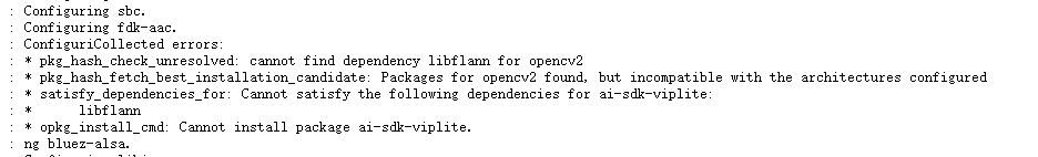
Acuity-Toolkit-Binary-6.6.1 版本已经非常老了,建议更新下版本,社区目前有 Radxa 提供的 NPU 开发环境:https://docs.radxa.com/en/cubie/a5e/app-dev/npu-dev/cubie-acuity-sdk
-
V853点亮d320fpc2403发布在 V Series
设备树配置
&lcd0 {
	base_config_start   = <1>;
	lcd_used            = <1>;

	lcd_driver_name     = "d320fpc2403";

	lcd_backlight       = <50>;
	lcd_if              = <4>;

	lcd_x               = <1024>;
	lcd_y               = <768>;
	lcd_width           = <64>;
	lcd_height          = <48>;
	lcd_dclk_freq       = <54>;

	lcd_pwm_used        = <1>;
	lcd_pwm_ch          = <9>;
	lcd_pwm_freq        = <5000>;
	lcd_pwm_pol         = <1>;
	lcd_pwm_max_limit   = <255>;

	lcd_hbp             = <50>;
	lcd_ht              = <1114>;
	lcd_hspw            = <10>;
	lcd_vbp             = <29>;
	lcd_vt              = <809>;
	lcd_vspw            = <8>;

	lcd_dsi_if          = <0>;
	lcd_dsi_lane        = <4>;
	lcd_dsi_format      = <0>;
	lcd_dsi_te          = <0>;
	lcd_dsi_eotp        = <0>;
	lcd_frm             = <0>;
	lcd_io_phase        = <0x0000>;
	lcd_hv_clk_phase    = <0>;
	lcd_hv_sync_polarity= <0>;
	lcd_gamma_en        = <0>;
	lcd_bright_curve_en = <0>;
	lcd_cmap_en         = <0>;
	lcdgamma4iep        = <22>;

	lcd_gpio_0          = <&pio PE 17 1 0 3 1>;
	pinctrl-0           = <&dsi4lane_pins_a>;
	pinctrl-1           = <&dsi4lane_pins_b>;
	base_config_end     = <1>;
};
驱动
/* drivers/video/sunxi/disp2/disp/lcd/d320fpc2403.c * * Copyright (c) 2025 Weidongshan <weidongshan@qq.com> * * d320fpc2403 panel driver * * This program is free software; you can redistribute it and/or modify * it under the terms of the GNU General Public License version 2 as * published by the Free Software Foundation. */ #include "d320fpc2403.h" static void lcd_power_on(u32 sel); static void lcd_power_off(u32 sel); static void lcd_bl_open(u32 sel); static void lcd_bl_close(u32 sel); static void lcd_panel_init(u32 sel); static void lcd_panel_exit(u32 sel); #define panel_reset(sel, val) sunxi_lcd_gpio_set_value(sel, 0, val) static void lcd_cfg_panel_info(struct panel_extend_para *info) { u32 i = 0, j = 0; u32 items; u8 lcd_gamma_tbl[][2] = { { 0, 0 }, { 15, 15 }, { 30, 30 }, { 45, 45 }, { 60, 60 }, { 75, 75 }, { 90, 90 }, { 105, 105 }, { 120, 120 }, { 135, 135 }, { 150, 150 }, { 165, 165 }, { 180, 180 }, { 195, 195 }, { 210, 210 }, { 225, 225 }, { 240, 240 }, { 255, 255 }, }; u32 lcd_cmap_tbl[2][3][4] = { { { LCD_CMAP_G0, LCD_CMAP_B1, LCD_CMAP_G2, LCD_CMAP_B3 }, { LCD_CMAP_B0, LCD_CMAP_R1, LCD_CMAP_B2, LCD_CMAP_R3 }, { LCD_CMAP_R0, LCD_CMAP_G1, LCD_CMAP_R2, LCD_CMAP_G3 }, }, { { LCD_CMAP_B3, LCD_CMAP_G2, LCD_CMAP_B1, LCD_CMAP_G0 }, { LCD_CMAP_R3, LCD_CMAP_B2, LCD_CMAP_R1, LCD_CMAP_B0 }, { LCD_CMAP_G3, LCD_CMAP_R2, LCD_CMAP_G1, LCD_CMAP_R0 }, }, }; items = sizeof(lcd_gamma_tbl) / 2; for (i = 0; i < items - 1; i++) { u32 num = lcd_gamma_tbl[i + 1][0] - lcd_gamma_tbl[i][0]; for (j = 0; j < num; j++) { u32 value = 0; value = lcd_gamma_tbl[i][1] + ((lcd_gamma_tbl[i + 1][1] - lcd_gamma_tbl[i][1]) * j) / num; info->lcd_gamma_tbl[lcd_gamma_tbl[i][0] + j] = (value << 16) + (value << 8) + value; } } info->lcd_gamma_tbl[255] = (lcd_gamma_tbl[items - 1][1] << 16) + (lcd_gamma_tbl[items - 1][1] << 8) + lcd_gamma_tbl[items - 1][1]; memcpy(info->lcd_cmap_tbl, lcd_cmap_tbl, sizeof(lcd_cmap_tbl)); } static s32 lcd_open_flow(u32 sel) { LCD_OPEN_FUNC(sel, lcd_power_on, 120); LCD_OPEN_FUNC(sel, lcd_panel_init, 10); LCD_OPEN_FUNC(sel, sunxi_lcd_tcon_enable, 10); LCD_OPEN_FUNC(sel, lcd_bl_open, 0); return 0; } static s32 lcd_close_flow(u32 sel) { LCD_CLOSE_FUNC(sel, lcd_bl_close, 0); LCD_CLOSE_FUNC(sel, lcd_panel_exit, 200); LCD_CLOSE_FUNC(sel, sunxi_lcd_tcon_disable, 0); LCD_CLOSE_FUNC(sel, lcd_power_off, 500); return 0; } static void lcd_power_on(u32 sel) { /* reset lcd by gpio */ panel_reset(sel, 1); sunxi_lcd_delay_ms(100); panel_reset(sel, 0); sunxi_lcd_delay_ms(500); panel_reset(sel, 1); sunxi_lcd_delay_ms(500); sunxi_lcd_pin_cfg(sel, 1); } static void lcd_power_off(u32 sel) { sunxi_lcd_pin_cfg(sel, 0); sunxi_lcd_delay_ms(20); panel_reset(sel, 0); sunxi_lcd_delay_ms(5); } static void lcd_bl_open(u32 sel) { sunxi_lcd_pwm_enable(sel); } static void lcd_bl_close(u32 sel) { sunxi_lcd_backlight_disable(sel); } #define REGFLAG_DELAY 0XFC #define REGFLAG_END_OF_TABLE 0xFD /* END OF REGISTERS MARKER */ struct LCM_setting_table { u8 cmd; u32 count; u8 para_list[64]; }; static struct LCM_setting_table lcm_initialization_setting[] = { { 0xdf, 3, { 0x91, 0x68, 0xf9 } }, { 0xde, 1, { 0x00 } }, // {0xc2, 1, {0x30}}, { 0xb2, 2, { 0x00, 0x7e } }, { 0xb3, 2, { 0x00, 0x7e } }, { 0xc1, 6, { 0x00, 0x10, 0x00, 0x00, 0x00, 0x00 } }, { 0xbb, 7, { 0x02, 0x24, 0x07, 0x61, 0x19, 0x44, 0x44 } }, { 0xbe, 2, { 0x1a, 0xf2 } }, { 0xc3, 14, { 0x10, 0x17, 0x5a, 0x17, 0x5a, 0x05, 0x05, 0x05, 0x05, 0x15, 0x15, 0x31, 0x05, 0xdf } }, { 0xc4, 7, { 0x11, 0x80, 0x00, 0xdf, 0x09, 0x06, 0x14 } }, { 0xce, 23, { 0x00, 0x03, 0x03, 0x03, 0x03, 0x03, 0x03, 0x03, 0x03, 0x03, 0x03, 0x03, 0x03, 0x03, 0x03, 0x03, 0x03, 0x03, 0x03, 0x03, 0x03, 0x0f, 0x03 } }, { 0xcf, 9, { 0x00, 0x01, 0x40, 0x01, 0xca, 0x01, 0xca, 0x01, 0xca } }, { 0xd0, 23, { 0x00, 0x1f, 0x1f, 0x1f, 0x1f, 0x1f, 0x1f, 0x1f, 0x1f, 0x1f, 0x1f, 0x03, 0x01, 0x05, 0x07, 0x09, 0x0b, 0x1e, 0x15, 0x1f, 0x1f, 0x15, 0x1f } }, { 0xd1, 23, { 0x00, 0x1f, 0x1f, 0x1f, 0x1f, 0x1f, 0x1f, 0x1f, 0x1f, 0x1f, 0x1f, 0x02, 0x00, 0x04, 0x06, 0x08, 0x0a, 0x1e, 0x15, 0x1f, 0x1f, 0x15, 0x1f } }, { 0xd2, 23, { 0x00, 0x1f, 0x1f, 0x1f, 0x1f, 0x1f, 0x1f, 0x1f, 0x1f, 0x1f, 0x1f, 0x00, 0x02, 0x0a, 0x08, 0x06, 0x04, 0x1f, 0x15, 0x1f, 0x1f, 0x15, 0x1e } }, { 0xd3, 23, { 0x00, 0x1f, 0x1f, 0x1f, 0x1f, 0x1f, 0x1f, 0x1f, 0x1f, 0x1f, 0x1f, 0x01, 0x03, 0x0b, 0x09, 0x07, 0x05, 0x1f, 0x15, 0x1f, 0x1f, 0x15, 0x1e } }, { 0xd4, 37, { 0x30, 0x00, 0x00, 0x04, 0x00, 0x06, 0x00, 0x00, 0x00, 0x00, 0x00, 0x03, 0x03, 0x00, 0x11, 0x00, 0x01, 0xc0, 0x04, 0x01, 0x01, 0x11, 0x80, 0x01, 0xc0, 0x05, 0x01, 0x01, 0x00, 0x00, 0x00, 0x04, 0x00, 0x06, 0x18, 0x02, 0xe3 } }, { 0xd5, 8, { 0x68, 0x73, 0x00, 0x08, 0x08, 0x00, 0x03, 0x00 } }, { 0xb7, 6, { 0x00, 0xd8, 0x00, 0x00, 0xd8, 0x00 } }, { 0xc8, 38, { 0x7f, 0x69, 0x5a, 0x4e, 0x4a, 0x3b, 0x40, 0x2a, 0x44, 0x43, 0x44, 0x63, 0x51, 0x59, 0x4c, 0x48, 0x3a, 0x28, 0x0f, 0x7f, 0x69, 0x5a, 0x4e, 0x4a, 0x3b, 0x40, 0x2a, 0x44, 0x43, 0x44, 0x63, 0x51, 0x59, 0x4c, 0x48, 0x3a, 0x28, 0x0f } }, { 0xde, 1, { 0x02 } }, { 0xbb, 4, { 0x00, 0x5b, 0x5c, 0x41 } }, { 0xb5, 3, { 0x00, 0x5a, 0x0a } }, { 0xc6, 1, { 0x22 } }, { 0xd7, 1, { 0x12 } }, { 0xe7, 2, { 0x00, 0x00 } }, { 0xde, 1, { 0x04 } }, { 0xcc, 1, { 0x02 } }, { 0xe7, 1, { 0x01 } }, { 0xde, 1, { 0x00 } }, { 0x35, 1, { 0x00 } }, { 0x11, 0, { 0x00 } }, { REGFLAG_DELAY, REGFLAG_DELAY, { 120 } }, { 0x29, 0, { 0x00 } }, { REGFLAG_DELAY, REGFLAG_DELAY, { 20 } }, { REGFLAG_END_OF_TABLE, REGFLAG_END_OF_TABLE, {} }, }; static void lcd_panel_init(u32 sel) { u32 i = 0; sunxi_lcd_dsi_clk_enable(sel); sunxi_lcd_delay_ms(100); for (i = 0;; i++) { if (lcm_initialization_setting[i].cmd == REGFLAG_END_OF_TABLE) break; else if (lcm_initialization_setting[i].cmd == REGFLAG_DELAY) sunxi_lcd_delay_ms(lcm_initialization_setting[i].count); else { dsi_dcs_wr(0, lcm_initialization_setting[i].cmd, lcm_initialization_setting[i].para_list, lcm_initialization_setting[i].count); } } } static void lcd_panel_exit(u32 sel) { sunxi_lcd_dsi_dcs_write_0para(sel, 0x28); sunxi_lcd_delay_ms(80); sunxi_lcd_dsi_dcs_write_0para(sel, 0x10); sunxi_lcd_delay_ms(50); } /*sel: 0:lcd0; 1:lcd1*/ static s32 lcd_user_defined_func(u32 sel, u32 para1, u32 para2, u32 para3) { return 0; } struct __lcd_panel d320fpc2403_panel = { /* panel driver name, must mach the name of * lcd_drv_name in sys_config.fex */ .name = "d320fpc2403", .func = { .cfg_panel_info = lcd_cfg_panel_info, .cfg_open_flow = lcd_open_flow, .cfg_close_flow = lcd_close_flow, .lcd_user_defined_func = lcd_user_defined_func, }, }; -
回复: 打包工具小细节发布在 编译和烧写问题专区
有full_img和programmer_img 转换工具,具体参考《Linux_MMC_NOR离线烧录_开发指南.pdf》《Linux_SLCNAND_UBI离线烧录_开发指南.pdf》
-
回复: 开机后显示驱动加载流程疑问?发布在 T Series
@tivon uboot下的显示驱动会被调用初始化屏幕显示logo,内核驱动里获取到屏幕已经被初始化,则显示驱动不会被调用,以免出现再次初始化屏幕导致闪屏的问题,达到平滑显示logo
-
回复: T113驱动480*854的mipi屏幕 uboot卡死发布在 T Series
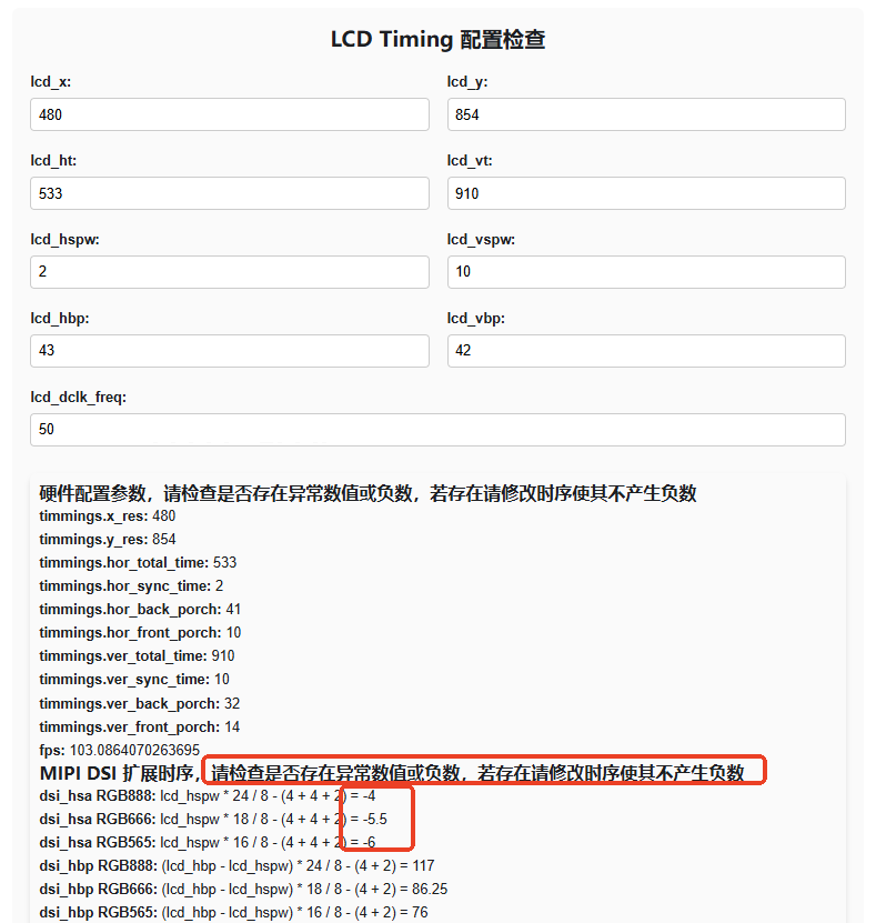
@fenglichaoa 在 T113驱动480*854的mipi屏幕 uboot卡死 中说:
50
https://docs.aw-ol.com/docs/tools/lcd_timing_checker
这组时序存在负数,会导致硬件产生超大数,卡死硬件,需要调整 lcd_hspw = 6
-
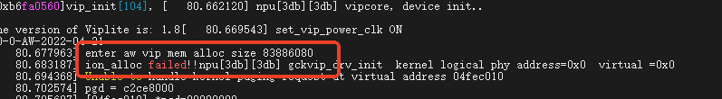
回复: V851se的enc异常求助 ionAlloc <ion_alloc_palloc_base:308>: ion_alloc do not opened, should call ion_alloc_open() before ion_alloc_alloc(size)发布在 V Series
ionAlloc <ion_alloc_palloc_base:308>: ion_alloc do not opened, should call ion_alloc_open() before ion_alloc_alloc(size)
报错都说明了,没有初始化ion就调用ion alloc
-
回复: 请教关于V821的SPI的问题-设备树发布在 V Series
-
821是 SPIF 控制器连接 NOR Flash,开启SPIF是由uboot动态修改设备树,SPIF是针对NOR,NAND存储器件优化的控制器,读取性能是普通SPI的一倍以上
-
是的
-
-
回复: v821切换到spi nand flash(XT26G01CWSIG) 系统无法启动发布在 V Series
&spi0 { pinctrl-0 = <&spi0_pins_default &spi0_pins_cs>; pinctrl-1 = <&spi0_pins_sleep>; pinctrl-names = "default", "sleep"; sunxi,spi-bus-mode = <SUNXI_SPI_BUS_NOR>; sunxi,spi-cs-mode = <SUNXI_SPI_CS_SOFT>; status = "okay"; spi_board0 { device_type = "spi_board0"; compatible = "spi-nor"; spi-max-frequency = <100000000>; m25p,fast-read = <1>; /*individual_lock;*/ reg = <0x0>; spi-rx-bus-width = <4>; spi-tx-bus-width = <4>; status = "disabled"; }; spi-nand@0 { compatible = "spi-nand"; spi-max-frequency=<100000000>; reg = <0x0>; spi-rx-bus-width=<0x04>; spi-tx-bus-width=<0x04>; status = "okay"; }; }; -
回复: v821切换到spi nand flash(XT26G01CWSIG) 系统无法启动发布在 V Series
@qy157 我的也是1.2 SDK
我的SPI驱动
[    0.413614] sunxi:spi-44025000.spi:[INFO]: spi manual set sample type_1, mode_1, delay_12
[    0.421012] sunxi-spi-ng 44025000.spi: 44025000.spi supply spi not found, using dummy regulator
[    0.429752] sunxi:spi-44025000.spi:[INFO]: bus num_0 mode_16 freq_100000000
[    0.436504] sunxi:spi-44025000.spi:[INFO]: cs num_1 mode_1
[    0.442165] sunxi:spi-44025000.spi:[WARN]: clk 100000000 not support, round to nearly 78769230
[    0.451312] sunxi:spi-44025000.spi:[WARN]: clk 100000000 not support, round to nearly 78769230
[    0.459519] sunxi:spi-44025000.spi:[INFO]: probe success (Version 2.5.5)

[    1.018678] sunxi:sunxi-spinand:[INFO]: AW SPINand MTD Layer Version: 2.7 20240110
[    1.027261] sunxi:sunxi-spinand-phy:[INFO]: AW SPINand Phy Layer Version: 1.13 20231109
[    1.036560] sunxi:sunxi-spinand-phy:[INFO]: detect munufacture from id table: XTX
[    1.045025] sunxi:sunxi-spinand-phy:[INFO]: detect spinand id: ffff110b ffffffff
[    1.053395] sunxi:sunxi-spinand-phy:[INFO]: ========== arch info ==========
[    1.061279] sunxi:sunxi-spinand-phy:[INFO]: Model:               XT26G01C
[    1.068961] sunxi:sunxi-spinand-phy:[INFO]: Munufacture:         XTX
[    1.076139] sunxi:sunxi-spinand-phy:[INFO]: DieCntPerChip:       1
[    1.083138] sunxi:sunxi-spinand-phy:[INFO]: BlkCntPerDie:        1024
[    1.090414] sunxi:sunxi-spinand-phy:[INFO]: PageCntPerBlk:       64
[    1.097512] sunxi:sunxi-spinand-phy:[INFO]: SectCntPerPage:      4
[    1.104509] sunxi:sunxi-spinand-phy:[INFO]: OobSizePerPage:      64
[    1.111589] sunxi:sunxi-spinand-phy:[INFO]: BadBlockFlag:        0x0
[    1.118781] sunxi:sunxi-spinand-phy:[INFO]: OperationOpt:        0x7
[    1.125958] sunxi:sunxi-spinand-phy:[INFO]: MaxEraseTimes:       50000
[    1.133348] sunxi:sunxi-spinand-phy:[INFO]: EccFlag:             0x0
[    1.140540] sunxi:sunxi-spinand-phy:[INFO]: EccType:             11
[    1.147637] sunxi:sunxi-spinand-phy:[INFO]: EccProtectedType:    1
[    1.154632] sunxi:sunxi-spinand-phy:[INFO]: ========================================
[    1.163372] sunxi:sunxi-spinand-phy:[INFO]:
[    1.168203] sunxi:sunxi-spinand-phy:[INFO]: ========== physical info ==========
[    1.176480] sunxi:sunxi-spinand-phy:[INFO]: TotalSize:    128 M
[    1.183169] sunxi:sunxi-spinand-phy:[INFO]: SectorSize:   512 B
[    1.189874] sunxi:sunxi-spinand-phy:[INFO]: PageSize:     2 K
[    1.196382] sunxi:sunxi-spinand-phy:[INFO]: BlockSize:    128 K
[    1.203072] sunxi:sunxi-spinand-phy:[INFO]: OOBSize:      64 B
[    1.209661] sunxi:sunxi-spinand-phy:[INFO]: ========================================
[    1.218502] sunxi:sunxi_mmc_host-44020000.sdmmc:[INFO]: sdc set ios:clk 0Hz bm PP pm OFF vdd 0 width 1 timing LEGACY(SDR12) dt B
[    1.231569] sunxi:sunxi-spinand-phy:[INFO]:
[    1.236410] sunxi:sunxi-spinand-phy:[INFO]: ========== logical info ==========
[    1.244615] sunxi:pin-42000000.pinctrl:[INFO]: Auto power withstand voltage configuration detected, automatically exit!
[    1.256810] sunxi:sunxi-spinand-phy:[INFO]: TotalSize:    128 M
[    1.263516] sunxi:sunxi-spinand-phy:[INFO]: SectorSize:   512 B
[    1.270263] sunxi:sunxi-spinand-phy:[INFO]: PageSize:     2 K
[    1.276805] sunxi:sunxi-spinand-phy:[INFO]: BlockSize:    128 K
[    1.283499] sunxi:sunxi-spinand-phy:[INFO]: OOBSize:      64 B
[    1.290090] sunxi:sunxi-spinand-phy:[INFO]: ========================================
[    1.298987] sunxi:sunxi-spinand-phy:[INFO]: block lock register: 0x00
[    1.307559] sunxi:sunxi-spinand-phy:[INFO]: feature register: 0x11
[    1.314652] sunxi:sunxi-spinand-phy:[INFO]: sunxi physic nand init end
你的 SPI 驱动
[    0.132161] sunxi:spi-44025000.spi:[INFO]: spi manual set sample type_1, mode_1, delay_15
[    0.132441] sunxi-spi-ng 44025000.spi: 44025000.spi supply spi not found, using dummy regulator
[    0.133298] sunxi:spi-44025000.spi:[INFO]: bus num_0 mode_16 freq_100000000
[    0.133573] sunxi:spi-44025000.spi:[INFO]: cs num_1 mode_1
[    0.134045] of_dma_request_slave_channel: dma-names property of node '/soc@2002000/spi@44025000' missing or empty
[    0.134926] sunxi:spi-44025000.spi:[ERR]: failed to request dma tx channel -19
[    0.135557] sunxi:spi-44025000.spi:[WARN]: clk 100000000 not support, round to nearly 78769230
[    0.136648] sunxi:spi-44025000.spi:[INFO]: probe success (Version 2.5.4)
[    0.327081] UBI error: cannot open mtd sys, error -2
[    0.327732] UBI: block: can't open volume on ubi0_-1, err=-19
可以看到,你的日志里连
AW SPINand MTD Layer Version: 2.7 20240110都没加载,所以SPI NAND 无法挂载 -
回复: v821切换到spi nand flash(XT26G01CWSIG) 系统无法启动发布在 V Series
测试了下,正常启动NAND,启动日志如下
[0]HELLO! BOOT0 is starting! [3]BOOT0 commit : c620eacf52-dirty [6]set pll start [10]set pll end [11]reset_src: rtc wdg rst [13]reset_src: det rst [15]reset_src: pwron rst [18]board init ok: use hosc 40M [21]rtc[5] value = 0xb0000000 [24]mode:0x1 sample delay:0xc [26]OperationOpt:7 [28]spinand quad mode error [31]spinand UBOOT_START_BLK_NUM 8 UBOOT_LAST_BLK_NUM 32 [35]BOOT_PARAM_OFFSET:0x500000 [39]boot param - magic error [42]DRAM use internal ZQ!! [44]ZQ value = 0x2e [46]DRAM BOOT DRIVE INFO: V1.02 [49]DRAM CLK = 520 MHz [51]DRAM Type = 2 (2:DDR2,3:DDR3) [54]DRAMC read ODT off. [56]DRAM ODT off. [58]ddr_clk0 = 1040 MHz [61]trefi: 7.8us [62]DRAM Size = 64 MB [66]DRAM simple test OK. [68]dram size =64 [70]mode:0x1 sample delay:0xc [73]OperationOpt:7 [74]spinand quad mode error [77]spinand UBOOT_START_BLK_NUM 8 UBOOT_LAST_BLK_NUM 32 [82]mode:0x1 sample delay:0xc [85]OperationOpt:7 [86]spinand quad mode error [89]spinand UBOOT_START_BLK_NUM 8 UBOOT_LAST_BLK_NUM 32 [94]block from 8 to 32 [220]Check is correct. Find a good uboot copy at block 8 [225]dma 0x2009d8c int is not used yet [228]dma 0x2009d8c int is free, you do not need to free it again [234]Entry_name = opensbi [237]Entry_name = u-boot [241]Entry_name = melis-elf [247]Jump to OpenSBI: opensbi_base = 0x80fc0000, dtb_base = 0x0, uboot_base = 0x82000000 OpenSBI 92310c8ed361641fa38c20bd0073be189e0f1282 ____ _____ ____ _____ / __ \ / ____| _ \_ _| | | | |_ __ ___ _ __ | (___ | |_) || | | | | | '_ \ / _ \ '_ \ \___ \| _ < | | | |__| | |_) | __/ | | |____) | |_) || |_ \____/| .__/ \___|_| |_|_____/|____/_____| | | |_| init msb region pma attribute Platform Name : sun300iw1 Platform Features : medeleg Platform HART Count : 1 Platform IPI Device : sunxi_plicsw Platform Timer Device : sunxi_plmt @ 40000000Hz Platform Console Device : sunxi_uart Platform HSM Device : --- Platform PMU Device : --- Platform Reboot Device : sunxi_wdt Platform Shutdown Device : sunxi_wdt Firmware Base : 0x80fc0400 Firmware Size : 75 KB Runtime SBI Version : 0.3 Domain0 Name : root Domain0 Boot HART : 0 Domain0 HARTs : 0* Domain0 Region00 : 0x80fc0000-0x80fdffff () Domain0 Region01 : 0x00000000-0xffffffff (R,W,X) Domain0 Next Address : 0x82000000 Domain0 Next Arg1 : 0x00000000 Domain0 Next Mode : S-mode Domain0 SysReset : yes Boot HART ID : 0 Boot HART Domain : root Boot HART ISA : rv32imafdcnsux Boot HART Features : scounteren,mcounteren,mcountinhibit,sscofpmf Boot HART PMP Count : 64 Boot HART PMP Granularity : 8 Boot HART PMP Address Bits: 31 Boot HART MHPM Count : 4 Boot HART MIDELEG : 0x00000222 Boot HART MEDELEG : 0x0000b109 U-Boot 2018.07-00001-g6c10d2cbd3-dirty (Aug 12 2025 - 15:29:57 +0800) Allwinner Technology I2C: ready [00.408]DRAM: 64 MiB [00.410]Relocation Offset is: 01f23000, reloc addr is: 83f23000 [00.418]secure enable bit: 0 [00.420]drivers/sunxi_power/pmu_axpnull.c pmu_axpnull_probe 26 axpdummy probe FDT ERROR:fdt_get_regulator_name:get property handle twi-supply error:FDT_ERR_INTERNAL [00.935]BMU: AXP2601 [00.937]CPU=960 MHz,PERI=3072 Mhz,AHB=192 Mhz, APB=96Mhz SPI ALL: ready [00.946]flash init start [00.948]workmode = 0,storage type = 0 [00.958]sunxi-spinand-phy: spinand sample_mode:1 sample_delay:c device nand0 <nand>, # parts = 4 #: name size offset mask_flags 0: boot0 0x00100000 0x00000000 1 1: uboot 0x00300000 0x00100000 1 2: secure_storage 0x00100000 0x00400000 1 3: sys 0x07b00000 0x00500000 0 active partition: nand0,0 - (boot0) 0x00100000 @ 0x00000000 defaults: mtdids : nand0=nand mtdparts: mtdparts=nand:1024k@0(boot0)ro,3072k@1048576(uboot)ro,1024k@4194304(secure_storage)ro,-(sys) [01.149]ubi0: attaching mtd4 [01.739]ubi0: scanning is finished [01.749]ubi0: attached mtd4 (name "sys", size 123 MiB) [01.754]ubi0: PEB size: 131072 bytes (128 KiB), LEB size: 126976 bytes [01.760]ubi0: min./max. I/O unit sizes: 2048/2048, sub-page size 2048 [01.767]ubi0: VID header offset: 2048 (aligned 2048), data offset: 4096 [01.773]ubi0: good PEBs: 980, bad PEBs: 4, corrupted PEBs: 0 [01.778]ubi0: user volume: 10, internal volumes: 1, max. volumes count: 128 [01.785]ubi0: max/mean erase counter: 2/1, WL threshold: 4096, image sequence number: 0 [01.793]ubi0: available PEBs: 0, total reserved PEBs: 980, PEBs reserved for bad PEB handling: 16 [01.801]sunxi flash init ok [02.054]Loading Environment from SUNXI_FLASH... OK [02.099]usb burn from boot delay time 0 [02.111]usb prepare ok [02.377]usb sof ok [02.379]usb probe ok [02.380]usb setup ok set address 0x36 set address 0x36 ok try to update [02.786]do_burn_from_boot usb : have no handshake List file under ULI/factory ** Unrecognized filesystem type ** [02.822]update bootcmd [02.858]change working_fdt 0x838e2ea0 to 0x838c2ea0 [02.874]## error: update_fdt_dram_para : FDT_ERR_NOTFOUND [02.880]update dts Info: gmac phy mode = rmii, phy_interface = 6 eth0 Warning: eth0 (eth0) using random MAC address - 3e:fd:af:11:ba:c6 Hit any key to stop autoboot: 0 [03.488]no vendor_boot partition is found Android's image name: sun300i_riscv32 Detect comp gzip ERROR: reserving fdt memory region failed (addr=80ffff00 size=100) [03.723] Starting kernel ... [ 0.000000] Linux version 5.4.220 (awol@tina-dev) (gcc version 10.4.0 (2024-02-02_nds32le-linux-glibc-v5d-bbc31ec98)) #4 PREEMPT Tue Aug 12 15:30:27 HKT 2025 [ 0.000000] printk: bootconsole [earlycon0] enabled [ 0.000000] Reserved memory: created CMA memory pool at 0x0000000083c00000, size 4 MiB [ 0.000000] OF: reserved mem: initialized node linux,cma, compatible id shared-dma-pool [ 0.000000] Reserved memory: created DMA memory pool at 0x0000000081200000, size 0 MiB [ 0.000000] OF: reserved mem: initialized node vdev0buffer@81200000, compatible id shared-dma-pool [ 0.000000] Reserved memory: created DMA memory pool at 0x0000000081646000, size 0 MiB [ 0.000000] OF: reserved mem: initialized node e907_rpbuf@81646000, compatible id shared-dma-pool [ 0.000000] Zone ranges: [ 0.000000] Normal [mem 0x0000000080000000-0x0000000083ffffff] [ 0.000000] Movable zone start for each node [ 0.000000] Early memory node ranges [ 0.000000] node 0: [mem 0x0000000080000000-0x0000000080ffefff] [ 0.000000] node 0: [mem 0x0000000081244000-0x0000000081643fff] [ 0.000000] node 0: [mem 0x000000008164e000-0x0000000083ffffff] [ 0.000000] Initmem setup node 0 [mem 0x0000000080000000-0x0000000083ffffff] [ 0.000000] On node 0 totalpages: 15793 [ 0.000000] Normal zone: 128 pages used for memmap [ 0.000000] Normal zone: 0 pages reserved [ 0.000000] Normal zone: 15793 pages, LIFO batch:3 [ 0.000000] SBI specification v0.3 detected [ 0.000000] SBI implementation ID=0x1 Version=0x10000 [ 0.000000] SBI v0.2 TIME extension detected [ 0.000000] SBI v0.2 IPI extension detected [ 0.000000] SBI v0.2 RFENCE extension detected [ 0.000000] SBI SRST extension detected [ 0.000000] riscv: base ISA extensions acdfim [ 0.000000] riscv: ELF capabilities acdfim [ 0.000000] pcpu-alloc: s0 r0 d32768 u32768 alloc=1*32768 [ 0.000000] pcpu-alloc: [0] 0 [ 0.000000] Built 1 zonelists, mobility grouping on. Total pages: 15665 [ 0.000000] Kernel command line: ubi.mtd=sys ubi.block=0,rootfs earlyprintk=sunxi-uart,0x42500000 initcall_debug=0 console=ttyS0,115200 loglevel=8 root=/dev/ubiblock0_7 rootwait rootfstype=squashfs init=/init rdinit=/rdinit partitions=mbr@ubi0_0:boot-resource@ubi0_1:env@ubi0_2:env-redund@ubi0_3:boot@ubi0_4:private@ubi0_5:riscv0@ubi0_6:rootfs@ubi0_7:rootfs_data@ubi0_8:UDISK@ubi0_9: cma=1M snum=0000000000000000000 mac_addr= wifi_mac= bt_mac= selinux=0 specialstr= gpt=1 arm-smmu-v3.disable_bypass=0 androidboot.serialno=0000000000000000000 androidboot.hardware=sun300iw1p1 boot_type=5 androidboot.boot_type=5 gpt=1 uboot_message=2018.07-00001-g6c10d2cbd3-dirty(08/12/2025-15:29:57) mbr_offset=1032192 bootreason=unknow aw-ubi-spinand.ubootblks=24 androidboot.dramfreq=520 androidboot.dramsize=64 mtdparts=nand:1024k@0(boot0)ro,3072k@1048576(uboot)ro,1024k@4194304(secure_storage)ro,-(sys) uboot_backup=ubootA [ 0.000000] Dentry cache hash table entries: 8192 (order: 3, 32768 bytes, linear) [ 0.000000] Inode-cache hash table entries: 4096 (order: 2, 16384 bytes, linear) [ 0.000000] Sorting __ex_table... [ 0.000000] mem auto-init: stack:off, heap alloc:off, heap free:off [ 0.000000] Memory: 27452K/63172K available (5134K kernel code, 357K rwdata, 1950K rodata, 172K init, 287K bss, 31624K reserved, 4096K cma-reserved) [ 0.000000] SLUB: HWalign=64, Order=0-3, MinObjects=0, CPUs=1, Nodes=1 [ 0.000000] rcu: Preemptible hierarchical RCU implementation. [ 0.000000] Tasks RCU enabled. [ 0.000000] rcu: RCU calculated value of scheduler-enlistment delay is 25 jiffies. [ 0.000000] NR_IRQS: 72, nr_irqs: 72, preallocated irqs: 0 [ 0.000000] plic: mapped 187 interrupts with 1 handlers for 2 contexts. [ 0.000000] sunxi:ccu-ng:[INFO]: Current HOSC rate is 40000000HZ [ 0.000000] AW BSP version: a3b0c2d69e, 2025-08-11 13:06:54 +0800 [ 0.000000] sunxi:ccu-ng:[INFO]: aon_ccu: sunxi ccu init OK [ 0.000000] sunxi:ccu-ng:[INFO]: sunxi ccu common driver version: 1.2.4 [ 0.000000] sunxi:ccu-ng:[INFO]: ccu: sunxi ccu init OK [ 0.000000] sunxi:ccu-ng:[INFO]: sunxi app ccu driver version: 0.7.2 [ 0.000000] riscv_timer_init_dt: Registering clocksource cpuid [0] hartid [0] [ 0.000000] clocksource: riscv_clocksource: mask: 0xffffffffffffffff max_cycles: 0x939a85c40, max_idle_ns: 440795202120 ns [ 0.000011] sched_clock: 64 bits at 40MHz, resolution 25ns, wraps every 4398046511100ns [ 0.008473] Console: colour dummy device 80x25 [ 0.012473] Calibrating delay loop (skipped), value calculated using timer frequency.. 80.00 BogoMIPS (lpj=160000) [ 0.022711] pid_max: default: 32768 minimum: 301 [ 0.027536] Mount-cache hash table entries: 1024 (order: 0, 4096 bytes, linear) [ 0.034601] Mountpoint-cache hash table entries: 1024 (order: 0, 4096 bytes, linear) [ 0.044585] rcu: Hierarchical SRCU implementation. [ 0.053527] devtmpfs: initialized [ 0.078054] clocksource: jiffies: mask: 0xffffffff max_cycles: 0xffffffff, max_idle_ns: 7645041785100000 ns [ 0.082252] futex hash table entries: 256 (order: -1, 3072 bytes, linear) [ 0.089236] pinctrl core: initialized pinctrl subsystem [ 0.102476] phys:80000000 low vir:c0000000 non-cache:dfc80000~e3c80000 [ 0.104464] NET: Registered protocol family 16 [ 0.113253] sunxi:ccu-ng:[INFO]: sunxi prcm ccu driver version: 0.0.4 [ 0.122260] sunxi:pin-42000000.pinctrl:[INFO]: pinctrl withstand voltage config mode=auto_hard [ 0.125298] sunxi:pin:[INFO]: sunxi pinctrl core driver version: 1.4.8 [ 0.132293] sunxi:pin:[INFO]: sunxi rtc-pinctrl version: 0.0.2 [ 0.140009] sunxi:pin-42000540.pinctrl:[INFO]: pinctrl withstand voltage config mode=auto_hard [ 0.150847] sunxi hwspinlock vbase:0x(ptrval) [ 0.181230] SCSI subsystem initialized [ 0.181650] usbcore: registered new interface driver usbfs [ 0.185528] usbcore: registered new interface driver hub [ 0.190353] usbcore: registered new device driver usb [ 0.195430] mc: Linux media interface: v0.10 [ 0.199500] videodev: Linux video capture interface: v2.00 [ 0.205746] Advanced Linux Sound Architecture Driver Initialized. [ 0.216000] sun6i-dma 43002000.dma-controller: sunxi dma probed, driver version: 1.2.11 [ 0.220776] sunxi-soc-regulator 4a000800.soc_pmu0: Supply for ldo1 (ldo1) resolved to itself [ 0.227351] ldo1: supplied by regulator-dummy [ 0.232403] ion_size_pool heap_size_pool@0: no small_source configurated, use cma as default [ 0.241950] sunxi:pin-42000000.pinctrl:[INFO]: Auto power withstand voltage configuration detected, automatically exit! [ 0.251068] sunxi-twi 42502000.twi0: 42502000.twi0 supply twi not found, using dummy regulator [ 0.260114] sunxi:twi-42502000.twi0:[INFO]: v2.7.9 probe success [ 0.266432] sunxi:pwm-42000c00.pwm:[INFO]: start probe [ 0.267149] sunxi:pwm-42000c00.pwm:[INFO]: pwmchip probe success [ 0.278460] clocksource: Switched to clocksource riscv_clocksource [ 0.287335] thermal_sys: Registered thermal governor 'fair_share' [ 0.287344] thermal_sys: Registered thermal governor 'bang_bang' [ 0.288670] thermal_sys: Registered thermal governor 'step_wise' [ 0.294704] thermal_sys: Registered thermal governor 'user_space' [ 0.300637] thermal_sys: Registered thermal governor 'power_allocator' [ 0.307346] thermal thermal_zone1: power_allocator: sustainable_power will be estimated [ 0.321990] sunxi_usb_udc 44100000.udc-controller: sunxi:sunxi_usb_udc UDC Inner DMA Feature - wordaddr: -1, extend: disabled [ 0.333426] NET: Registered protocol family 2 [ 0.337145] IP idents hash table entries: 2048 (order: 2, 16384 bytes, linear) [ 0.345016] tcp_listen_portaddr_hash hash table entries: 512 (order: 0, 4096 bytes, linear) [ 0.352427] TCP established hash table entries: 1024 (order: 0, 4096 bytes, linear) [ 0.359972] TCP bind hash table entries: 1024 (order: 0, 4096 bytes, linear) [ 0.366989] TCP: Hash tables configured (established 1024 bind 1024) [ 0.373405] UDP hash table entries: 256 (order: 0, 4096 bytes, linear) [ 0.379794] UDP-Lite hash table entries: 256 (order: 0, 4096 bytes, linear) [ 0.387007] NET: Registered protocol family 1 [ 0.391836] RPC: Registered named UNIX socket transport module. [ 0.397017] RPC: Registered udp transport module. [ 0.401607] RPC: Registered tcp transport module. [ 0.406304] RPC: Registered tcp NFSv4.1 backchannel transport module. [ 0.413614] sunxi:spi-44025000.spi:[INFO]: spi manual set sample type_1, mode_1, delay_12 [ 0.421012] sunxi-spi-ng 44025000.spi: 44025000.spi supply spi not found, using dummy regulator [ 0.429752] sunxi:spi-44025000.spi:[INFO]: bus num_0 mode_16 freq_100000000 [ 0.436504] sunxi:spi-44025000.spi:[INFO]: cs num_1 mode_1 [ 0.442165] sunxi:spi-44025000.spi:[WARN]: clk 100000000 not support, round to nearly 78769230 [ 0.451312] sunxi:spi-44025000.spi:[WARN]: clk 100000000 not support, round to nearly 78769230 [ 0.459519] sunxi:spi-44025000.spi:[INFO]: probe success (Version 2.5.5) [ 0.469435] workingset: timestamp_bits=30 max_order=13 bucket_order=0 [ 0.484916] squashfs: version 4.0 (2009/01/31) Phillip Lougher [ 0.486566] NFS: Registering the id_resolver key type [ 0.490248] Key type id_resolver registered [ 0.494393] Key type id_legacy registered [ 0.498351] nfs4filelayout_init: NFSv4 File Layout Driver Registering... [ 0.505034] nfs4flexfilelayout_init: NFSv4 Flexfile Layout Driver Registering... [ 0.512724] fuse: init (API version 7.31) [ 0.517883] NET: Registered protocol family 38 [ 0.520924] Block layer SCSI generic (bsg) driver version 0.4 loaded (major 248) [ 0.528157] io scheduler mq-deadline registered [ 0.532647] io scheduler kyber registered [ 0.559966] loop: module loaded [ 0.560986] ehci_hcd: USB 2.0 'Enhanced' Host Controller (EHCI) Driver [ 0.564099] ehci-platform: EHCI generic platform driver [ 0.569754] ohci_hcd: USB 1.1 'Open' Host Controller (OHCI) Driver [ 0.575427] ohci-platform: OHCI generic platform driver [ 0.582004] usbcore: registered new interface driver uas [ 0.586066] usbcore: registered new interface driver usb-storage [ 0.591997] i2c /dev entries driver [ 0.596628] usbcore: registered new interface driver usbhid [ 0.600921] usbhid: USB HID core driver [ 0.606390] uart-ng uart-ng0: uart-ng0 supply uart not found, using dummy regulator [ 0.612609] sunxi:uart-ng-uart-ng0:[INFO]: cannot get the TX DMA channel! [ 0.619134] sunxi:uart-ng-uart-ng0:[INFO]: cannot get the RX DMA channel! [ 0.625908] sunxi:uart-ng:[INFO]: sunxi uart-ng driver version: 1.1.10 [ 0.632371] uart-ng0: ttyS0 at MMIO 0x42500000 (irq = 134, base_baud = 12000000) is a SUNXI [ 0.640682] sunxi:uart-ng-uart-ng0:[INFO]: console setup baud 115200 parity n bits 8, flow n [ 0.649051] sunxi:uart-ng-uart-ng0:[INFO]: uart0, select set 0, baud 115200, uartclk 192000000 beyond rance[24000000, 120000000] [ 0.660666] printk: console [ttyS0] enabled [ 0.660666] printk: console [ttyS0] enabled [ 0.670917] printk: bootconsole [earlycon0] disabled [ 0.670917] printk: bootconsole [earlycon0] disabled [ 0.681979] sunxi:rtc-4a000c00.rtc:[WARN]: Fail to get clock 'rtc-1k' [ 0.692901] sunxi:rtc-4a000c00.rtc:[WARN]: Fail to get clock 'rtc-spi' [ 0.700394] sunxi:rtc:[INFO]: Saving SoC boot-reason: COLD-BOOT [ 0.707210] sunxi:rtc-4a000c00.rtc:[INFO]: errata__fix_alarm_day_reg_default_value(): ALARM0_DAY_REG=0, set it to 1 [ 0.719011] sunxi:rtc-4a000c00.rtc:[WARN]: Warning: Using internal RC 16M clock source. Time may be inaccurate! [ 0.730404] sunxi:rtc-4a000c00.rtc:[WARN]: Warning: Using internal RC 16M clock source. Time may be inaccurate! [ 0.742084] sunxi:rtc-4a000c00.rtc:[WARN]: Warning: Using internal RC 16M clock source. Time may be inaccurate! [ 0.753512] sunxi:rtc-4a000c00.rtc:[WARN]: Warning: Using internal RC 16M clock source. Time may be inaccurate! [ 0.764935] sunxi:rtc-4a000c00.rtc:[WARN]: Warning: Using internal RC 16M clock source. Time may be inaccurate! [ 0.777021] sunxi-rtc 4a000c00.rtc: registered as rtc0 [ 0.782939] sunxi:rtc_sun300iw1_frun_counter:[ERR]: rtc_frun_counter_init(83): rtc frun counter src not from extern32k osc [ 0.795407] sunxi:rtc-4a000c00.rtc:[WARN]: clocksource not work: rtc free running counter [ 0.804659] sunxi:rtc-4a000c00.rtc:[INFO]: sunxi rtc probed [ 0.812830] sunxi-wdt 4a001000.watchdog: Watchdog enabled (timeout=300 sec, nowayout=0), driver version: 1.0.5 [ 0.826837] sunxi:sunxi_mmc_host-44020000.sdmmc:[INFO]: SD/MMC/SDIO Host Controller Driver(v5.55 2024-08-26 15:32) [ 0.838848] sunxi:sunxi_mmc_host-44020000.sdmmc:[INFO]: ctl-spec-caps 8 [ 0.846404] sunxi:sunxi_mmc_host-44020000.sdmmc:[INFO]: No vmmc regulator found [ 0.854697] sunxi:sunxi_mmc_host-44020000.sdmmc:[INFO]: No vqmmc regulator found [ 0.863074] sunxi:sunxi_mmc_host-44020000.sdmmc:[INFO]: No vdmmc regulator found [ 0.871477] sunxi:sunxi_mmc_host-44020000.sdmmc:[INFO]: No vd33sw regulator found [ 0.879926] sunxi:sunxi_mmc_host-44020000.sdmmc:[INFO]: No vd18sw regulator found [ 0.888389] sunxi:sunxi_mmc_host-44020000.sdmmc:[INFO]: No vq33sw regulator found [ 0.896838] sunxi:sunxi_mmc_host-44020000.sdmmc:[INFO]: No vq18sw regulator found [ 0.905302] sunxi:sunxi_mmc_host-44020000.sdmmc:[ERR]: manual set ocr [ 0.912630] sunxi:sunxi_mmc_host-44020000.sdmmc:[WARN]: Cann't get pin bias hs pinstate,check if needed [ 0.923362] sunxi:sunxi_mmc_host-44020000.sdmmc:[ERR]: Could not get store clock [ 0.931752] sunxi:sunxi_mmc_host-44020000.sdmmc:[ERR]: Could not get msi_lite clock [ 0.940967] sunxi-mmc 44020000.sdmmc: Got CD GPIO [ 0.946499] sunxi-mmc 44020000.sdmmc: sunxi:sunxi_mmc_hostcd-set-debounce is missing, function is no used [ 0.957969] sunxi:sunxi_mmc_host-44020000.sdmmc:[INFO]: sdc set ios:clk 0Hz bm PP pm UP vdd 21 width 1 timing LEGACY(SDR12) dt B [ 0.983495] sunxi:sunxi_mmc_host-44020000.sdmmc:[INFO]: sdc set ios:clk 400000Hz bm PP pm ON vdd 21 width 1 timing LEGACY(SDR12) dt B [ 1.009792] sunxi:sunxi_mmc_host-44020000.sdmmc:[INFO]: detmode:gpio irq [ 1.018678] sunxi:sunxi-spinand:[INFO]: AW SPINand MTD Layer Version: 2.7 20240110 [ 1.027261] sunxi:sunxi-spinand-phy:[INFO]: AW SPINand Phy Layer Version: 1.13 20231109 [ 1.036560] sunxi:sunxi-spinand-phy:[INFO]: detect munufacture from id table: XTX [ 1.045025] sunxi:sunxi-spinand-phy:[INFO]: detect spinand id: ffff110b ffffffff [ 1.053395] sunxi:sunxi-spinand-phy:[INFO]: ========== arch info ========== [ 1.061279] sunxi:sunxi-spinand-phy:[INFO]: Model: XT26G01C [ 1.068961] sunxi:sunxi-spinand-phy:[INFO]: Munufacture: XTX [ 1.076139] sunxi:sunxi-spinand-phy:[INFO]: DieCntPerChip: 1 [ 1.083138] sunxi:sunxi-spinand-phy:[INFO]: BlkCntPerDie: 1024 [ 1.090414] sunxi:sunxi-spinand-phy:[INFO]: PageCntPerBlk: 64 [ 1.097512] sunxi:sunxi-spinand-phy:[INFO]: SectCntPerPage: 4 [ 1.104509] sunxi:sunxi-spinand-phy:[INFO]: OobSizePerPage: 64 [ 1.111589] sunxi:sunxi-spinand-phy:[INFO]: BadBlockFlag: 0x0 [ 1.118781] sunxi:sunxi-spinand-phy:[INFO]: OperationOpt: 0x7 [ 1.125958] sunxi:sunxi-spinand-phy:[INFO]: MaxEraseTimes: 50000 [ 1.133348] sunxi:sunxi-spinand-phy:[INFO]: EccFlag: 0x0 [ 1.140540] sunxi:sunxi-spinand-phy:[INFO]: EccType: 11 [ 1.147637] sunxi:sunxi-spinand-phy:[INFO]: EccProtectedType: 1 [ 1.154632] sunxi:sunxi-spinand-phy:[INFO]: ======================================== [ 1.163372] sunxi:sunxi-spinand-phy:[INFO]: [ 1.168203] sunxi:sunxi-spinand-phy:[INFO]: ========== physical info ========== [ 1.176480] sunxi:sunxi-spinand-phy:[INFO]: TotalSize: 128 M [ 1.183169] sunxi:sunxi-spinand-phy:[INFO]: SectorSize: 512 B [ 1.189874] sunxi:sunxi-spinand-phy:[INFO]: PageSize: 2 K [ 1.196382] sunxi:sunxi-spinand-phy:[INFO]: BlockSize: 128 K [ 1.203072] sunxi:sunxi-spinand-phy:[INFO]: OOBSize: 64 B [ 1.209661] sunxi:sunxi-spinand-phy:[INFO]: ======================================== [ 1.218502] sunxi:sunxi_mmc_host-44020000.sdmmc:[INFO]: sdc set ios:clk 0Hz bm PP pm OFF vdd 0 width 1 timing LEGACY(SDR12) dt B [ 1.231569] sunxi:sunxi-spinand-phy:[INFO]: [ 1.236410] sunxi:sunxi-spinand-phy:[INFO]: ========== logical info ========== [ 1.244615] sunxi:pin-42000000.pinctrl:[INFO]: Auto power withstand voltage configuration detected, automatically exit! [ 1.256810] sunxi:sunxi-spinand-phy:[INFO]: TotalSize: 128 M [ 1.263516] sunxi:sunxi-spinand-phy:[INFO]: SectorSize: 512 B [ 1.270263] sunxi:sunxi-spinand-phy:[INFO]: PageSize: 2 K [ 1.276805] sunxi:sunxi-spinand-phy:[INFO]: BlockSize: 128 K [ 1.283499] sunxi:sunxi-spinand-phy:[INFO]: OOBSize: 64 B [ 1.290090] sunxi:sunxi-spinand-phy:[INFO]: ======================================== [ 1.298987] sunxi:sunxi-spinand-phy:[INFO]: block lock register: 0x00 [ 1.307559] sunxi:sunxi-spinand-phy:[INFO]: feature register: 0x11 [ 1.314652] sunxi:sunxi-spinand-phy:[INFO]: sunxi physic nand init end [ 1.322545] Creating 4 MTD partitions on "nand": [ 1.327877] 0x000000000000-0x000000100000 : "boot0" [ 1.347915] 0x000000100000-0x000000400000 : "uboot" [ 1.379900] 0x000000400000-0x000000500000 : "secure_storage" [ 1.399878] 0x000000500000-0x000008000000 : "sys" [ 1.544147] sunxi:sunxi-spinand-phy:[INFO]: phy blk 245 is bad [ 1.690664] sunxi:sunxi-spinand-phy:[INFO]: phy blk 440 is bad [ 1.827269] sunxi:sunxi-spinand-phy:[INFO]: phy blk 635 is bad [ 1.969603] sunxi:sunxi-spinand-phy:[INFO]: phy blk 830 is bad [ 2.117528] sunxi:g2d_sunxi:[INFO]: [G2D]: rcq version initialized.major:244 [ 2.125590] sunxi:g2d_sunxi:[INFO]: [G2D]: g2d_module_init [ 2.133796] sunxi:gmac-44500000.gmac:[INFO]: Dts rx-delay: 0 [ 2.140309] sunxi:gmac-44500000.gmac:[INFO]: Not found delay-maps in dts [ 2.147893] sunxi:gmac-44500000.gmac:[INFO]: Get max-mtu: 950 [ 2.155382] sunxi:gmac-eth0:[INFO]: Use random mac address [ 2.162208] sunxi:gpadc:[INFO]: sunxi_gpadc_init(): 2236: gpadc class register success [ 2.171963] sunxi:gpadc-42009000.gpadc0:[WARN]: warn: sample rate not set [ 2.180074] input: sunxi-gpadc0/channel0/input0 as /devices/platform/soc@2002000/42009000.gpadc0/input/input0 [ 2.192253] sunxi:gpadc-42009000.gpadc0:[INFO]: sunxi_gpadc probe success [ 2.206829] sunxi-msgbox 43033000.msgbox: sunxi:sunxi_msgboxsunxi_msgbox_probe(): sunxi msgbox start probe [ 2.218073] sunxi-msgbox 43033000.msgbox: sunxi:sunxi_msgboxsunxi_msgbox_probe(): sunxi msgbox probe success [ 2.230771] sunxi-rproc 43030000.e907_rproc: sunxi rproc driver 2.4.3 [ 2.238295] sunxi-rproc 43030000.e907_rproc: rv-cfg base: 0x43030000, va: 0xdfc55000 [ 2.247222] sunxi-rproc 43030000.e907_rproc: find rproc standby error [ 2.254819] sunxi-rproc 43030000.e907_rproc: timeout_ms: 6000 [ 2.261400] sunxi-rproc 43030000.e907_rproc: reset_type: 2 [ 2.267669] sunxi-rproc 43030000.e907_rproc: reg: 43031000 [ 2.274572] sunxi-rproc 43030000.e907_rproc: irq_num: 164 [ 2.280983] sunxi-rproc 43030000.e907_rproc: panic_on_timeout: 1 [ 2.288113] sunxi-rproc 43030000.e907_rproc: The bootloader doesn't boot up the remoteproc when auto-boot is enabled! [ 2.300141] sunxi-rproc 43030000.e907_rproc: is_using_kernel_fw: 0 [ 2.307290] remoteproc remoteproc0: e907_rproc is available [ 2.313790] sunxi-rproc 43030000.e907_rproc: sunxi rproc driver probe ok [ 2.322256] sunxi-rpbuf-controller rpbuf_controller0@0: assigned reserved memory node e907_rpbuf@81646000 [ 2.334074] [ADDR_MGT] addr_mgt_probe: module version: v1.0.13 [ 2.341603] [ADDR_MGT] addr_mgt_probe: success. [ 2.347172] sunxi:sunxi_startup_info-startup_info:[INFO]: startup source record: cold_boot [ 2.356939] NET: Registered protocol family 17 [ 2.362057] NET: Registered protocol family 15 [ 2.367265] Key type dns_resolver registered [ 2.395290] ubi0: attaching mtd3 [ 2.414519] sunxi:ccu-ng-4a000000.prcm_ccu:[ERR]: enable extern 32k error [ 2.422354] sunxi:ccu-ng-4a000000.prcm_ccu:[WARN]: enable extern 32k error, change rccal [ 3.042557] random: crng init done [ 3.602697] ubi0: scanning is finished [ 3.620458] ubi0 warning: ubi_eba_init: cannot reserve enough PEBs for bad PEB handling, reserved 16, need 36 [ 3.635294] ubi0: attached mtd3 (name "sys", size 123 MiB) [ 3.641574] ubi0: PEB size: 131072 bytes (128 KiB), LEB size: 126976 bytes [ 3.649362] ubi0: min./max. I/O unit sizes: 2048/2048, sub-page size 2048 [ 3.657062] ubi0: VID header offset: 2048 (aligned 2048), data offset: 4096 [ 3.664936] ubi0: good PEBs: 980, bad PEBs: 4, corrupted PEBs: 0 [ 3.671735] ubi0: user volume: 10, internal volumes: 1, max. volumes count: 128 [ 3.679999] ubi0: max/mean erase counter: 2/1, WL threshold: 4096, image sequence number: 0 [ 3.689437] ubi0: available PEBs: 0, total reserved PEBs: 980, PEBs reserved for bad PEB handling: 16 [ 3.699868] ubi0: background thread "ubi_bgt0d" started, PID 45 [ 3.709256] block ubiblock0_7: created from ubi0:7(rootfs) [ 3.715596] sunxi:rtc-4a000c00.rtc:[WARN]: Warning: Using internal RC 16M clock source. Time may be inaccurate! [ 3.727065] sunxi-rtc 4a000c00.rtc: setting system clock to 1970-01-01T00:00:08 UTC (8) [ 3.737914] sunxi:sound-common:[WARN]: 326 pacfg_level_trig_init(): pa-pin-msleep1-0 get failed, default 0 [ 3.750718] sunxi:sound-i2s:[WARN]: 2206 snd_sunxi_dts_params_init(): clk-en-post-delay missing [ 3.760600] sunxi:sound-i2s:[WARN]: 2214 snd_sunxi_dts_params_init(): clk-keep missing [ 3.770356] sunxi:sound-mach:[WARN]: 372 asoc_simple_parse_ucfmt(): set data late to default [ 3.780423] debugfs: Directory 'soc@2002000:codec_plat' with parent 'audiocodec' already present! [ 3.790778] sunxi-snd-mach soc@2002000:codec_mach: 42030000.codec <-> soc@2002000:codec_plat mapping ok [ 3.803000] sunxi:sound-mach:[WARN]: 372 asoc_simple_parse_ucfmt(): set data late to default [ 3.812660] sunxi-snd-mach soc@2002000:i2s0_mach: No 'sound-dai' property [ 3.820722] debugfs: Directory '42032000.i2s0_plat' with parent 'sndi2s0' already present! [ 3.830363] sunxi-snd-mach soc@2002000:i2s0_mach: snd-soc-dummy-dai <-> 42032000.i2s0_plat mapping ok [ 4.023782] ALSA device list: [ 4.027257] #0: audiocodec [ 4.030547] #1: sndi2s0 [ 4.033762] sunxi:uart-ng-uart-ng0:[INFO]: uart0, select set 0, baud 115200, uartclk 192000000 beyond rance[24000000, 120000000] [ 4.052878] VFS: Mounted root (squashfs filesystem) readonly on device 254:0. [ 4.067067] devtmpfs: mounted [ 4.070705] Freeing unused kernel memory: 172K [ 4.075775] This architecture does not have kernel memory protection. [ 4.083069] Run /init as init process mount: mounting none on /dev failed: Resource busy mbr@ubi0_0:boot-resource@ubi0_1:env@ubi0_2:env-redund@ubi0_3:boot@ubi0_4:private@ubi0_5:riscv0@ubi0_6:rootfs@ubi0_7:rootfs_data@ubi0_8:UDISK@ubi0_9: [ 4.626213] UBIFS (ubi0:8): Mounting in unauthenticated mode [ 4.633237] UBIFS (ubi0:8): background thread "ubifs_bgt0_8" started, PID 83 [ 4.701713] UBIFS (ubi0:8): recovery needed [ 4.804595] UBIFS (ubi0:8): recovery completed [ 4.810397] UBIFS (ubi0:8): UBIFS: mounted UBI device 0, volume 8, name "rootfs_data" [ 4.819351] UBIFS (ubi0:8): LEB size: 126976 bytes (124 KiB), min./max. I/O unit sizes: 2048 bytes/2048 bytes [ 4.830657] UBIFS (ubi0:8): FS size: 4063232 bytes (3 MiB, 32 LEBs), journal size 1015809 bytes (0 MiB, 6 LEBs) [ 4.842176] UBIFS (ubi0:8): reserved for root: 191915 bytes (187 KiB) [ 4.849495] UBIFS (ubi0:8): media format: w5/r0 (latest is w5/r0), UUID 424C0888-89F6-4FAB-9AD1-5CDE86100932, small LPT model Cannot get MTD information for /dev/by-name/env Cannot get MTD information for /dev/by-name/env-redund [ 4.891360] overlayfs: upper fs does not support xattr, falling back to index=off and metacopy=off. init started: BusyBox v1.33.2 (2025-07-09 02:10:56 UTC) starting pid 99, tty '': '/etc/init.d/rcS boot' [ 4.985831] UBIFS (ubi0:9): Mounting in unauthenticated mode [ 4.992663] UBIFS (ubi0:9): background thread "ubifs_bgt0_9" started, PID 104 [ 5.038705] sunxi_usb_udc 44100000.udc-controller: 44100000.udc-controller supply udc not found, using dummy regulator [ 5.073903] UBIFS (ubi0:9): recovery needed [ 5.120995] UBIFS (ubi0:9): recovery completed [ 5.126773] UBIFS (ubi0:9): UBIFS: mounted UBI device 0, volume 9, name "UDISK" [ 5.135252] UBIFS (ubi0:9): LEB size: 126976 bytes (124 KiB), min./max. I/O unit sizes: 2048 bytes/2048 bytes [ 5.146495] UBIFS (ubi0:9): FS size: 53202944 bytes (50 MiB, 419 LEBs), journal size 2666496 bytes (2 MiB, 21 LEBs) [ 5.158282] UBIFS (ubi0:9): reserved for root: 2512906 bytes (2454 KiB) [ 5.165791] UBIFS (ubi0:9): media format: w5/r0 (latest is w5/r0), UUID 6883688F-2146-4B9E-A8A4-C73BDED33919, small LPT model ------run rc.final file----- Load mpp modules [ 5.401512] sunxi:vin:[WARN]: sensor_helper_probe: cannot get sensor0_cameravdd supply, setting it to NULL! [ 5.425962] sunxi:vin:[WARN]: sensor_helper_probe: cannot get sensor0_iovdd supply, setting it to NULL! [ 5.445572] sunxi:vin:[WARN]: sensor_helper_probe: cannot get sensor0_avdd supply, setting it to NULL! [ 5.465086] sunxi:vin:[WARN]: sensor_helper_probe: cannot get sensor0_dvdd supply, setting it to NULL! sh: write error: Invalid argument [ 5.540911] file system registered [ 5.590915] udc 44100000.udc-controller: failed to start g1: -19 sh: write error: No such device sh: 0000000000000000000: unknown operand [ 5.694148] read descriptors [ 5.697669] read strings [ 5.991427] sunxi:vin:[WARN]: get csi isp clk fail [ 5.996962] sunxi:vin:[WARN]: get csi isp src clk fail [ 6.004206] sunxi:vin:[INFO]: [gc1084_mipi]PWR_ON! [ 6.011447] sunxi:twi-42502000.twi0:[ERR]: drv-mode: Timeout when sending 9th SCL clk [ 6.020281] sunxi:twi-42502000.twi0:[ERR]: drv mode: TWI BUS error state is drv:0x1 eng:0x20 [ 6.029914] sunxi:twi-42502000.twi0:[ERR]: drv-mode: xfer failed (dev addr:0x37) [ 6.038442] sunxi:twi-42502000.twi0:[ERR]: drv-mode: Timeout when sending 9th SCL clk [ 6.047267] sunxi:twi-42502000.twi0:[ERR]: drv mode: TWI BUS error state is drv:0x1 eng:0x20 [ 6.056852] sunxi:twi-42502000.twi0:[ERR]: drv-mode: xfer failed (dev addr:0x37) [ 6.065320] sunxi:twi-42502000.twi0:[ERR]: drv-mode: Timeout when sending 9th SCL clk [ 6.074142] sunxi:twi-42502000.twi0:[ERR]: drv mode: TWI BUS error state is drv:0x1 eng:0x20 [ 6.083741] sunxi:twi-42502000.twi0:[ERR]: drv-mode: xfer failed (dev addr:0x37) [ 6.092194] sunxi:vin:[INFO]: [VIN_DEV_I2C]gc1084_mipi read retry 3, read addr is 0x3f0 [ 6.304889] configfs-gadget gadget: high-speed config #1: c [ 6.320554] sunxi:twi-42502000.twi0:[ERR]: drv-mode: Timeout when sending 9th SCL clk [ 6.329383] sunxi:twi-42502000.twi0:[ERR]: drv mode: TWI BUS error state is drv:0x1 eng:0x20 [ 6.338934] sunxi:twi-42502000.twi0:[ERR]: drv-mode: xfer failed (dev addr:0x37) [ 6.347407] sunxi:twi-42502000.twi0:[ERR]: drv-mode: Timeout when sending 9th SCL clk [ 6.356254] sunxi:twi-42502000.twi0:[ERR]: drv mode: TWI BUS error state is drv:0x1 eng:0x20 [ 6.365802] sunxi:twi-42502000.twi0:[ERR]: drv-mode: xfer failed (dev addr:0x37) [ 6.374258] sunxi:twi-42502000.twi0:[ERR]: drv-mode: Timeout when sending 9th SCL clk [ 6.383103] sunxi:twi-42502000.twi0:[ERR]: drv mode: TWI BUS error state is drv:0x1 eng:0x20 [ 6.392646] sunxi:twi-42502000.twi0:[ERR]: drv-mode: xfer failed (dev addr:0x37) [ 6.401032] sunxi:vin:[INFO]: [VIN_DEV_I2C]gc1084_mipi read retry 3, read addr is 0x3f0 [ 6.629528] sunxi:twi-42502000.twi0:[ERR]: drv-mode: Timeout when sending 9th SCL clk [ 6.638352] sunxi:twi-42502000.twi0:[ERR]: drv mode: TWI BUS error state is drv:0x1 eng:0x20 [ 6.647893] sunxi:twi-42502000.twi0:[ERR]: drv-mode: xfer failed (dev addr:0x37) [ 6.656324] sunxi:twi-42502000.twi0:[ERR]: drv-mode: Timeout when sending 9th SCL clk [ 6.665147] sunxi:twi-42502000.twi0:[ERR]: drv mode: TWI BUS error state is drv:0x1 eng:0x20 [ 6.674716] sunxi:twi-42502000.twi0:[ERR]: drv-mode: xfer failed (dev addr:0x37) [ 6.683172] sunxi:twi-42502000.twi0:[ERR]: drv-mode: Timeout when sending 9th SCL clk [ 6.691995] sunxi:twi-42502000.twi0:[ERR]: drv mode: TWI BUS error state is drv:0x1 eng:0x20 [ 6.701562] sunxi:twi-42502000.twi0:[ERR]: drv-mode: xfer failed (dev addr:0x37) [ 6.709948] sunxi:vin:[INFO]: [VIN_DEV_I2C]gc1084_mipi read retry 3, read addr is 0x3f0 [ 6.938532] sunxi:twi-42502000.twi0:[ERR]: drv-mode: Timeout when sending 9th SCL clk [ 6.947355] sunxi:twi-42502000.twi0:[ERR]: drv mode: TWI BUS error state is drv:0x1 eng:0x20 [ 6.956897] sunxi:twi-42502000.twi0:[ERR]: drv-mode: xfer failed (dev addr:0x37) [ 6.965330] sunxi:twi-42502000.twi0:[ERR]: drv-mode: Timeout when sending 9th SCL clk [ 6.974152] sunxi:twi-42502000.twi0:[ERR]: drv mode: TWI BUS error state is drv:0x1 eng:0x20 [ 6.983693] sunxi:twi-42502000.twi0:[ERR]: drv-mode: xfer failed (dev addr:0x37) [ 6.992125] sunxi:twi-42502000.twi0:[ERR]: drv-mode: Timeout when sending 9th SCL clk [ 7.000959] sunxi:twi-42502000.twi0:[ERR]: drv mode: TWI BUS error state is drv:0x1 eng:0x20 [ 7.010499] sunxi:twi-42502000.twi0:[ERR]: drv-mode: xfer failed (dev addr:0x37) [ 7.018903] sunxi:vin:[INFO]: [VIN_DEV_I2C]gc1084_mipi read retry 3, read addr is 0x3f0 [ 7.027950] sunxi:vin:[ERR]: [gc1084_mipi]chip found is not an target chip. [ 7.035824] sunxi:vin:[INFO]: [gc1084_mipi]PWR_OFF! [ 7.044241] sunxi:vin:[ERR]: registering gc1084_mipi, No such device! [ 7.051630] sunxi:vin:[INFO]: vinc1 is null [ 7.056488] sunxi:vin:[INFO]: vinc5 is null [ 7.103033] sunxi:VE:[INFO]: 2238 sunxi_cedar_init(): sunxi cedar version 1.1 [ 7.111654] sunxi:VE:[INFO]: 2160 sunxi_cedar_probe(): probe ve [ 7.118788] sunxi-cedar 41c0e000.ve: 41c0e000.ve supply ve not found, using dummy regulator [ 7.134896] remoteproc remoteproc0: powering up e907_rproc [ 7.141252] remoteproc remoteproc0: using internal firmware, skip checking here [ 7.440622] remoteproc remoteproc0: loading fw from partition riscv0 [ 7.448248] sunxi-rproc 43030000.e907_rproc: handle vendor resource, type: 129 [ 7.456517] sunxi-rproc 43030000.e907_rproc: add trace mem 'aw_trace_log', da: 0x8112ef00, len: 4096 [ 7.466980] remoteproc remoteproc0: Physical address cast in 32bit to fit resource table format [ 7.476867] remoteproc remoteproc0: firmware version: UTS - Tue, 12 Aug 2025 15:29:39 +0800 [ 7.476867] Compile Time - 15:29:39 [ 7.494044] sunxi-rproc 43030000.e907_rproc: boot address: 0x81001c00 [ 7.501579] remoteproc0#vdev0buffer: assigned reserved memory node vdev0buffer@81200000 [ 7.512111] virtio_rpmsg_bus virtio0: rpmsg host is online [ 7.518523] remoteproc0#vdev0buffer: registered virtio0 (type 7) [ 7.525426] remoteproc remoteproc0: remote processor e907_rproc is now up Load usb modules Load wifi modules [ 7.624077] [xradio_mod_init,690][XRADIO_ALWY] xradio wlan version:XR_V1.0.0.250218 [ 7.632781] [xradio_core_init,543][XRADIO_ALWY] xradio core init [ 7.678924] virtio_rpmsg_bus virtio0: creating channel sunxi,rpmsg_ctrl addr 0x400 [ 7.703298] virtio_rpmsg_bus virtio0: creating channel rpbuf-service addr 0x401 [ 7.711867] rpbuf_service_rpmsg virtio0.rpbuf-service.-1.1025: rpmsg device parent 0: virtio0 [ 7.721558] rpbuf_service_rpmsg virtio0.rpbuf-service.-1.1025: rpmsg device parent 1: remoteproc0#vdev0buffer [ 7.732769] rpbuf_service_rpmsg virtio0.rpbuf-service.-1.1025: rpmsg device parent 2: remoteproc0 [ 7.742798] rpbuf_service_rpmsg virtio0.rpbuf-service.-1.1025: rpmsg device parent 3: 43030000.e907_rproc [ 7.764082] sunxi-rpbuf-controller rpbuf_controller0@0: buffer "xradio_mtx": NULL -> remote_dummy_buffers [ 7.774976] sunxi-rpbuf-controller rpbuf_controller0@0: buffer "xradio_mrx": NULL -> remote_dummy_buffers [ 7.785842] virtio_rpmsg_bus virtio0: creating channel xrlink_rpmsg addr 0x402 [ 7.794276] [xradio_rpmsg_init,191][IO] xrlink rpmsg creat succeed [ 7.805452] sunxi-rpbuf-controller rpbuf_controller0@0: "xradio_mrx" allocate payload memory: va 0x099423c5, pa 0x0000000083c08000, len 20480 [ 7.820444] sunxi-rpbuf-controller rpbuf_controller0@0: buffer "xradio_mrx" (id:1): remote_dummy_buffers -> buffers [ 7.838613] sunxi-rpbuf-controller rpbuf_controller0@0: "xradio_mtx" allocate payload memory: va 0x54b08cbd, pa 0x0000000083c10000, len 12288 [ 7.860998] sunxi-rpbuf-controller rpbuf_controller0@0: buffer "xradio_mtx" (id:0): remote_dummy_buffers -> buffers [ 7.873515] [xradio_rpbuf_init,555][IO] xrlink master rpbuf creat succeed [ 7.881313] [xradio_platform_init,84][PLAT] xradio_platform_init sucess 0xc1e55200 [ 7.890015] [xradio_core_init,550][XRADIO_ALWY] xradio_plat c1e55200 [ 7.897273] [xradio_core_init,553][XRADIO_ALWY] xradio add_net_dev [ 7.905778] [xradio_core_init,560][XRADIO_ALWY] xradio debug com init [ 7.913252] [xradio_core_init,564][XRADIO_ALWY] xradio queue init [ 7.920200] [xradio_core_init,569][XRADIO_ALWY] xradio platform on [ 7.927205] [xradio_core_init,574][XRADIO_ALWY] register tx and rx task [ 7.935177] [xradio_core_init,579][XRADIO_ALWY] up cmd init [ 7.941625] [xradio_core_init,584][XRADIO_ALWY] low cmd init [ 7.948061] [xradio_core_init,589][XRADIO_ALWY] hand way [ 7.955170] [xraido_low_cmd_dev_hand_way,129][CMD] Host hand way dev success. [ 7.963276] [xradio_core_init,594][XRADIO_ALWY] xradio core init Suceess [ 7.971517] [xradio_set_kernel_macaddr,454][XRADIO_ALWY] MACADDR=94:0a:31:b7:1e:e8 [ 7.980326] [xradio_core_init,610][XRADIO_ALWY] AP_ADDR=94:0a:31:b7:9e:e9 [ 7.988024] [xradio_core_init,617][XRADIO_ALWY] wlan device is opening... [ 8.147806] [xradio_core_init,622][XRADIO_ALWY] wlan device is ready [ 8.155096] ======== XRADIO WIFI OPEN ======== Starting wifi_deamon....: WINF: wifimanger verion:2.0.8.5 20250812-07:18:33 c3e9e83 WINF: ************************************** WINF: * Copyright (c) 2019-2025 Allwinner Technology Co., Ltd. ALL rights reserved WINF: * version: 2.0.8.5 20250812-07:18:33 c3e9e83 WINF: * module name: UNKNOWN (D) WINF: * wifimg support mode:(sta | ap | --- | --- | ------ | -------) WINF: * module support mode:(sta | ap | --- | --- | ------ | -------) WINF: * actual support mode:(sta | ap | --- | --- | ------ | -------) WINF: ************************************** WINF: wifi mode sta on success WINF: wifi on sta success WINF: wifi set auto reconnect enable success mount: mounting /dev/mmcblk0p1 on /mnt/extsd failed: No such file or directory starting pid 204, tty '/dev/console': '-/bin/sh' BusyBox v1.33.2 (2025-07-09 02:10:56 UTC) built-in shell (ash) _____ _ __ _ |_ _||_| ___ _ _ | | |_| ___ _ _ _ _ | | _ | || | | |__ | || || | ||_'_| | | | || | || _ | |_____||_||_|_||___||_,_| |_| |_||_|_||_|_| Tina is Based on OpenWrt! ---------------------------------------------- Tina Linux (5.0, r16776-9575252c49) ---------------------------------------------- root@(none):/# root@(none):/# -
回复: v821切换到spi nand flash(XT26G01CWSIG) 系统无法启动发布在 V Series
看日志是内核整套ubi都没开起来,可以再次运行quick_config,重新编译SDK测试下
-
回复: v821 sample_smartIPC_demo无法正常运行发布在 V Series
为啥说无法正常运行,这不是码流都已经编码保存了
record.c:220] <openFile> record[0] open file[/mnt/extsd/mainStream_0.raw] success! -
回复: D1-h裸机下修改主频无效发布在 其它全志芯片讨论区
主频很低,大概3MHz 是GPIO翻转的主频吗?
核心最低主频是24MHz,不可能低到3M的D1-H 的 GPIO 是通过 APB 连到 CPU 的,其运行速率与CPU不是同步的
-
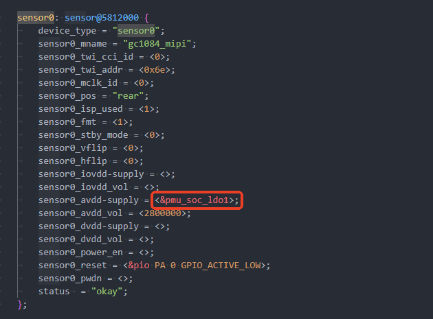
回复: Tina V821 Linux系统使用V4L2打开摄像头发布在 V Series
参考 platform/allwinner/eyesee-mpp/middleware/sun300iw1/sample/sample_driverVipp
v4l2 的硬件实现是vipp -
回复: 求问:V851SE Tinyvision 修改为SPI NAND flash 没有root登录发布在 V Series
@jaying SD NAND和SPI NAND是不一样的东西,引脚也不一样
-
回复: 求问:V851SE Tinyvision 修改为SPI NAND flash 没有root登录发布在 V Series
Tinyvision 怎么修改 SPINAND的?飞线么,默认焊盘不支持挂nand的
-
回复: T113 tft lcd显示不正常发布在 T Series
dclk太高了,改分频参数,原来6改成16
disp2/disp/de/lowlevel_v2x/disp_al.c
{LCD_IF_HV, 16, 1, 1, 0}, -
回复: All available flash: 0. default 1. nor Choice [default]: 0 INFO: Prepare toolchain ... ERROR: Prepare toolchain error!发布在 V Series
请使用
source build/envsetup.sh
lunch -
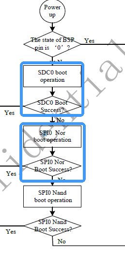
回复: V3s的USB启动问题发布在 编译和烧写问题专区
@jeff123a BSP引脚在V3s QFP封装并未引出,他是一个独立的引脚,在BGA封装的V3上硬件叫做 UBOOT 脚,位于 T9 球,并不是SPI_MISO引脚
-
回复: v821解码输出用AW_MPI_VDEC_SetRotate旋转90°,AW_ION_IOC_NEW_ALLOC出错,解码旋转不能用这个函数吗?发布在 V Series
AW_ION_IOC_NEW_ALLOC 内存不够了,需要增加ion内存,修改设备树 size_pool相关节点
https://docs.aw-ol.com/docs/soc/v821/software/sdk_sys_conf#预留内存 -
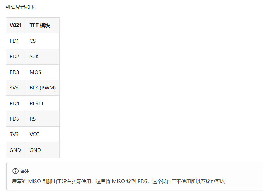
回复: V821驱动8080 8bit接口TFT屏,画面割裂。发布在 V Series
试一下加上刷cache的接口
diff --git a/drivers/video/sunxi/disp2/disp/dev_disp.c b/drivers/video/sunxi/disp2/disp/dev_disp.c index 8ddbd28..c084de0 100644 --- a/drivers/video/sunxi/disp2/disp/dev_disp.c +++ b/drivers/video/sunxi/disp2/disp/dev_disp.c @@ -3158,6 +3158,11 @@ static int disp_mem_request(int sel, u32 size) #endif } +void disp_flush_cache(dma_addr_t addr, u32 len) +{ + dma_sync_single_for_device(g_disp_drv.dev, addr, len, DMA_TO_DEVICE); +} + static int disp_mem_release(int sel) { if (sel >= DISP_MEM_NUM || sel < 0) { diff --git a/drivers/video/sunxi/disp2/disp/dev_disp.h b/drivers/video/sunxi/disp2/disp/dev_disp.h index 6478db3..cdd250f 100644 --- a/drivers/video/sunxi/disp2/disp/dev_disp.h +++ b/drivers/video/sunxi/disp2/disp/dev_disp.h @@ -327,6 +327,7 @@ int disp_resume(struct device *dev); s32 disp_create_heap(u32 pHeapHead, u32 pHeapHeadPhy, u32 nHeapSize); void *disp_malloc(u32 num_bytes, void *phy_addr); void disp_free(void *virt_addr, void *phys_addr, u32 num_bytes); +void disp_flush_cache(dma_addr_t addr, u32 len); extern s32 disp_register_sync_proc(void (*proc) (u32)); extern s32 disp_unregister_sync_proc(void (*proc) (u32)); diff --git a/drivers/video/sunxi/disp2/disp/fb_platform.c b/drivers/video/sunxi/disp2/disp/fb_platform.c index 7e95e74..c935ecc 100644 --- a/drivers/video/sunxi/disp2/disp/fb_platform.c +++ b/drivers/video/sunxi/disp2/disp/fb_platform.c @@ -341,6 +341,8 @@ int platform_update_fb_output(void *hw_info, const struct fb_var_screeninfo *var struct disp_manager *mgr; mutex_lock(&info->lock); info->config.info.fb.crop.y = ((long long)var->yoffset) << 32; + + disp_flush_cache(info->dma_mem.device_addr,info->size); #if IS_ENABLED(CONFIG_AW_DISP2_FB_HW_ROTATION_SUPPORT) if (info->fb_rot) fb_g2d_rot_apply(info->fb_rot, &info->config, var->yoffset); -
回复: E907配置问题:menuconfig里找不到SUNXI remote processor support,E907编译不过发布在 V Series
SUNXI remote processor support是kernel_menuconfig
-
回复: v821无法烧录nor flash发布在 V Series
flash operation timed outflash 无响应,物料型号是否是在物料表中的支持型号?另外可以尝试降频等操作