anl是glibc的部件,musl没有
YuzukiTsuru 发布的帖子
-
回复: 编译应用程序报错arm-openwrt-linux-muslgnueabi/bin/ld: cannot find -lanl发布在 V Series
-
回复: tina下 Map the console to the primary display device选项,启动崩溃发布在 Linux
4.9 kernel的fbcon有bug,调用fbcon但是没启用font选项,有一个加载顺序的问题。不建议使用
-
回复: F133A(D1s)如何使用GPIO:PG4 PG5?发布在 MR Series
ash: write error: Invalid argument 参数无效看一下是不是kernel配置gpio有问题,建议启用debug输出看看
-
回复: 全志 u-boot.fex 文件的作用发布在 编译和烧写问题专区
路径有些修改,本质上还是这些同样的操作,现在用的是boot_package.fex,把uboot打包进来了
[package] item=opensbi, fw_jump.bin item=u-boot, u-boot-sun20iw1p1.bin -
回复: tina3.5.1 R11 TF卡启动出错发布在 A Series
@cube_work 在 tina3.5.1 R11 TF卡启动出错 中说:
[913]Entry_name = optee
[916]unknow boot package file
[919]Ready to disable icache.boot_package.cfg里配置下uboot
-
回复: tina如何更改wifi的sdc总线?发布在 MR Series
参考这个,配置SDC2的WIFI
/* * Allwinner Technology CO., Ltd. sun20iw1p1 fpga. * * fpga support. */ /dts-v1/; #include "sun20iw1p1u1.dtsi" /{ compatible = "allwinner,d1", "arm,sun20iw1p1", "allwinner,sun20iw1p1"; aliases { dsp0 = &dsp0; dsp0_gpio_int= &dsp0_gpio_int; }; dsp0: dsp0 { compatible = "allwinner,sun20iw1-dsp"; status = "disabled"; }; dsp0_gpio_int: dsp0_gpio_int { compatible = "allwinner,sun20iw1-dsp-gpio-int"; pin-group = "PB", "PC", "PD", "PE"; status = "disabled"; }; reg_vdd_cpu: vdd-cpu { compatible = "sunxi-pwm-regulator"; pwms = <&pwm 0 5000 1>; regulator-name = "vdd_cpu"; regulator-min-microvolt = <810000>; regulator-max-microvolt = <1160000>; regulator-ramp-delay = <25>; regulator-always-on; regulator-boot-on; status = "okay"; }; reg_usb1_vbus: usb1-vbus { compatible = "regulator-fixed"; regulator-name = "usb1-vbus"; regulator-min-microvolt = <5000000>; regulator-max-microvolt = <5000000>; regulator-enable-ramp-delay = <1000>; gpio = <&pio PB 3 GPIO_ACTIVE_HIGH>; enable-active-high; }; }; &CPU0 { cpu-supply = <®_vdd_cpu>; }; &pio { sdc0_pins_a: sdc0@0 { allwinner,pins = "PF0", "PF1", "PF2", "PF3", "PF4", "PF5"; allwinner,function = "sdc0"; allwinner,muxsel = <2>; allwinner,drive = <3>; allwinner,pull = <1>; pins = "PF0", "PF1", "PF2", "PF3", "PF4", "PF5"; function = "sdc0"; drive-strength = <30>; bias-pull-up; power-source = <3300>; }; sdc0_pins_b: sdc0@1 { pins = "PF0", "PF1", "PF2", "PF3", "PF4", "PF5"; function = "sdc0"; drive-strength = <30>; bias-pull-up; power-source = <1800>; }; sdc0_pins_c: sdc0@2 { pins = "PF0", "PF1", "PF2", "PF3", "PF4", "PF5"; function = "gpio_in"; }; /* TODO: add jtag pin */ sdc0_pins_d: sdc0@3 { pins = "PF2", "PF4"; function = "uart0"; drive-strength = <10>; bias-pull-up; }; sdc0_pins_e: sdc0@4 { pins = "PF0", "PF1", "PF3", "PF5"; function = "jtag"; drive-strength = <10>; bias-pull-up; }; sdc1_pins_a: sdc1@0 { pins = "PG0", "PG1", "PG2", "PG3", "PG4", "PG5"; function = "sdc1"; drive-strength = <30>; bias-pull-up; }; sdc1_pins_b: sdc1@1 { pins = "PG0", "PG1", "PG2", "PG3", "PG4", "PG5"; function = "gpio_in"; }; sdc2_pins_a: sdc2@0 { pins = "PC2", "PC3", "PC4", "PC5", "PC6", "PC7"; function = "sdc2"; drive-strength = <30>; bias-pull-up; }; sdc2_pins_b: sdc2@1 { pins = "PC2", "PC3", "PC4", "PC5", "PC6", "PC7"; function = "gpio_in"; }; wlan_pins_a:wlan@0 { pins = "PG11"; function = "clk_fanout1"; }; uart0_pins_a: uart0_pins@0 { /* For EVB1 board */ pins = "PE2", "PE3"; function = "uart0"; drive-strength = <10>; bias-pull-up; }; uart0_pins_b: uart0_pins@1 { /* For EVB1 board */ pins = "PE2", "PE3"; function = "gpio_in"; }; uart1_pins_a: uart1_pins@0 { /* For EVB1 board */ pins = "PE8", "PE9", "PE10", "PE11"; function = "uart1"; drive-strength = <10>; bias-pull-up; }; uart1_pins_b: uart1_pins@1 { /* For EVB1 board */ pins = "PE8", "PE9", "PE10", "PE11"; function = "gpio_in"; }; uart2_pins_a: uart2_pins@0 { /* For EVB1 board */ pins = "PC0", "PC1"; function = "uart2"; drive-strength = <10>; bias-pull-up; }; uart2_pins_b: uart2_pins@1 { /* For EVB1 board */ pins = "PC0", "PC1"; function = "gpio_in"; }; uart3_pins_a: uart3_pins@0 { /* For EVB1 board */ pins = "PB6", "PB7"; function = "uart3"; muxsel = <7>; drive-strength = <10>; bias-pull-up; }; uart3_pins_b: uart3_pins@1 { /* For EVB1 board */ pins = "PB6", "PB7"; function = "gpio_in"; }; twi0_pins_a: twi0@0 { pins = "PB10", "PB11"; /*sck sda*/ function = "twi0"; drive-strength = <10>; }; twi0_pins_b: twi0@1 { pins = "PB10", "PB11"; function = "gpio_in"; }; twi1_pins_a: twi1@0 { pins = "PB4", "PB5"; function = "twi1"; drive-strength = <10>; }; twi1_pins_b: twi1@1 { pins = "PB4", "PB5"; function = "gpio_in"; }; twi2_pins_a: twi2@0 { pins = "PE12", "PE13"; function = "twi2"; drive-strength = <10>; }; twi2_pins_b: twi2@1 { pins = "PE12", "PE13"; function = "gpio_in"; }; twi3_pins_a: twi3@0 { pins = "PE6", "PE7"; function = "twi3"; drive-strength = <10>; }; twi3_pins_b: twi3@1 { pins = "PE6", "PE7"; function = "gpio_in"; }; gmac_pins_a: gmac@0 { pins = "PG0", "PG1", "PG2", "PG3", "PG4", "PG5", "PG6", "PG7", "PG8", "PG9", "PG10", "PG12", "PG13", "PG14", "PG15"; function = "gmac0"; drive-strength = <10>; }; gmac_pins_b: gmac@1 { pins = "PG0", "PG1", "PG2", "PG3", "PG4", "PG5", "PG6", "PG7", "PG8", "PG9", "PG10", "PG12", "PG13", "PG14", "PG15"; function = "gpio_in"; }; dmic_pins_a: dmic@0 { /* DMIC_PIN: CLK, DATA0, DATA1, DATA2, DATA3*/ pins = "PB12", "PB11", "PB10", "PE14", "PB8"; function = "dmic"; drive-strength = <20>; bias-disable; }; dmic_pins_b: dmic@1 { pins = "PB12", "PB11", "PB10", "PE14", "PB8"; function = "io_disabled"; drive-strength = <20>; bias-disable; }; daudio0_pins_a: daudio0@0 { pins = "PE17", "PE16", "PE15", "PE14", "PE13"; function = "i2s0"; drive-strength = <20>; bias-disable; }; daudio0_pins_b: daudio0_sleep@0 { pins = "PE17", "PE16", "PE15", "PE14", "PE13"; function = "io_disabled"; drive-strength = <20>; bias-disable; }; daudio1_pins_a: daudio1@0 { pins = "PG11", "PG12", "PG13", "PG14", "PG15"; function = "i2s1"; drive-strength = <20>; bias-disable; }; daudio1_pins_b: daudio1_sleep@0 { pins = "PG11", "PG12", "PG13", "PG14", "PG15"; function = "io_disabled"; drive-strength = <20>; bias-disable; }; daudio2_pins_a: daudio2@0 { /* I2S_PIN: MCLK, BCLK, LRCK */ pins = "PF6", "PF3", "PF5"; function = "i2s2"; drive-strength = <20>; bias-disable; }; daudio2_pins_b: daudio2@1 { /* I2S_PIN: DOUT0 */ pins = "PF1"; function = "i2s2_dout"; drive-strength = <20>; bias-disable; }; daudio2_pins_c: daudio2@2 { /* I2S_PIN: DIN0 */ pins = "PF0"; function = "i2s2_din"; drive-strength = <20>; bias-disable; }; daudio2_pins_d: daudio2_sleep@0 { pins = "PF6", "PF3", "PF5", "PF1", "PF0"; function = "io_disabled"; drive-strength = <20>; bias-disable; }; spdif_pins_a: spdif@0 { /* SPDIF_PIN: SPDIF_OUT */ pins = "PG18"; function = "spdif"; drive-strength = <20>; bias-disable; }; spdif_pins_b: spdif_sleep@0 { pins = "PG18"; function = "io_disabled"; drive-strength = <20>; bias-disable; }; spi0_pins_a: spi0@0 { pins = "PC2", "PC4", "PC5"; /* clk, mosi, miso */ function = "spi0"; muxsel = <2>; drive-strength = <20>; }; spi0_pins_b: spi0@1 { pins = "PC3", "PC7", "PC6"; function = "spi0"; muxsel = <2>; drive-strength = <20>; bias-pull-up; /* cs, hold, wp should be pulled up */ }; spi0_pins_c: spi0@2 { pins = "PC2", "PC3", "PC4", "PC5","PC6", "PC7"; function = "gpio_in"; muxsel = <0>; drive-strength = <10>; }; spi1_pins_a: spi1@0 { pins = "PD11", "PD12", "PD13"; /* clk, mosi, miso */ function = "spi1"; drive-strength = <10>; }; spi1_pins_b: spi1@1 { pins = "PD10", "PD14", "PD15"; function = "spi1"; drive-strength = <10>; bias-pull-up; /* cs, hold, wp should be pulled up */ }; spi1_pins_c: spi1@2 { pins = "PD10", "PD11", "PD12", "PD13","PD14", "PD15"; function = "gpio_in"; drive-strength = <10>; }; ledc_pins_a: ledc@0 { pins = "PC0"; function = "ledc"; drive-strength = <10>; }; ledc_pins_b: ledc@1 { pins = "PC0"; function = "gpio_in"; }; pwm0_pin_a: pwm0@0 { pins = "PD16"; function = "pwm0"; drive-strength = <10>; bias-pull-up; }; pwm0_pin_b: pwm0@1 { pins = "PD16"; function = "gpio_in"; bias-disable; }; pwm2_pin_a: pwm2@0 { pins = "PD18"; function = "pwm2"; drive-strength = <10>; bias-pull-up; }; pwm2_pin_b: pwm2@1 { pins = "PD18"; function = "gpio_out"; }; pwm7_pin_a: pwm7@0 { pins = "PD22"; function = "pwm7"; drive-strength = <10>; bias-pull-up; }; pwm7_pin_b: pwm7@1 { pins = "PD22"; function = "gpio_in"; }; s_cir0_pins_a: s_cir@0 { pins = "PB7"; function = "ir"; drive-strength = <10>; bias-pull-up; }; s_cir0_pins_b: s_cir@1 { pins = "PB7"; function = "gpio_in"; }; ir1_pins_a: ir1@0 { pins = "PB0"; function = "ir"; drive-strength = <10>; bias-pull-up; }; ir1_pins_b: ir1@1 { pins = "PB0"; function = "gpio_in"; }; can0_pins_a: can0_pins_a@0 { pins = "PB2", "PB3"; function = "can0"; drive-strength = <10>; bias-pull-up; }; can0_pins_b: can0_pins_b@1 { pins = "PB2", "PB3"; function = "gpio_in"; }; can1_pins_a: can1_pins_a@0 { pins = "PB4", "PB5"; function = "can1"; drive-strength = <10>; bias-pull-up; }; can1_pins_b: can1_pins_b@1 { pins = "PB4", "PB5"; function = "gpio_in"; }; }; &uart0 { pinctrl-names = "default", "sleep"; pinctrl-0 = <&uart0_pins_a>; pinctrl-1 = <&uart0_pins_b>; status = "okay"; }; &uart1 { pinctrl-names = "default", "sleep"; pinctrl-0 = <&uart1_pins_a>; pinctrl-1 = <&uart1_pins_b>; status = "okay"; }; &uart2 { pinctrl-names = "default", "sleep"; pinctrl-0 = <&uart2_pins_a>; pinctrl-1 = <&uart2_pins_b>; status = "disabled"; }; &uart3 { pinctrl-names = "default", "sleep"; pinctrl-0 = <&uart3_pins_a>; pinctrl-1 = <&uart3_pins_b>; status = "disabled"; }; &soc { card0_boot_para@2 { /* * Avoid dtc compiling warnings. * @TODO: Developer should modify this to the actual value */ reg = <0x0 0x2 0x0 0x0>; device_type = "card0_boot_para"; card_ctrl = <0x0>; card_high_speed = <0x1>; card_line = <0x4>; pinctrl-0 = <&sdc0_pins_a>; }; rfkill: rfkill@0 { compatible = "allwinner,sunxi-rfkill"; chip_en; power_en; pinctrl-0 = <&wlan_pins_a>; pinctrl-names = "default"; status = "okay"; wlan: wlan@0 { compatible = "allwinner,sunxi-wlan"; wlan_busnum = <0x2>; wlan_regon = <&pio PE 4 GPIO_ACTIVE_HIGH>; wlan_hostwake = <&pio PE 0 GPIO_ACTIVE_HIGH>; /*wlan_power = "VCC-3V3";*/ /*wlan_power_vol = <3300000>;*/ /*interrupt-parent = <&pio>; interrupts = < PG 10 IRQ_TYPE_LEVEL_HIGH>;*/ wakeup-source; }; bt: bt@0 { compatible = "allwinner,sunxi-bt"; /*bt_power_num = <0x01>;*/ /*bt_power = "axp803-dldo1";*/ /*bt_io_regulator = "axp803-dldo1";*/ /*bt_io_vol = <3300000>;*/ /*bt_power_vol = <330000>;*/ bt_rst_n = <&pio PE 5 GPIO_ACTIVE_LOW>; status = "okay"; }; }; btlpm: btlpm@0 { compatible = "allwinner,sunxi-btlpm"; uart_index = <0x1>; bt_wake = <&pio PE 7 GPIO_ACTIVE_HIGH>; bt_hostwake = <&pio PE 6 GPIO_ACTIVE_HIGH>; status = "okay"; }; addr_mgt: addr_mgt@0 { compatible = "allwinner,sunxi-addr_mgt"; type_addr_wifi = <0x0>; type_addr_bt = <0x0>; type_addr_eth = <0x0>; status = "okay"; }; sdc2: sdmmc@4022000 { compatible = "allwinner,sunxi-mmc-v5p3x"; device_type = "sdc2"; reg = <0x0 0x04022000 0x0 0x1000>; interrupts-extended = <&plic0 58 IRQ_TYPE_LEVEL_HIGH>; clocks = <&dcxo24M>, <&ccu CLK_PLL_PERIPH0_2X>, <&ccu CLK_MMC2>, <&ccu CLK_BUS_MMC2>; clock-names = "osc24m","pll_periph","mmc","ahb"; resets = <&ccu RST_BUS_MMC2>; reset-names = "rst"; pinctrl-names = "default","sleep"; pinctrl-0 = <&sdc2_pins_a>; pinctrl-1 = <&sdc2_pins_b>; max-frequency = <50000000>; bus-width = <4>; cap-sd-highspeed; no-mmc; keep-power-in-suspend; sunxi-dly-52M-ddr4 = <1 0 0 0 2>; sunxi-dly-104M = <1 0 0 0 1>; sunxi-dly-208M = <1 0 0 0 1>; status = "disabled"; }; }; &sdc2 { bus-width = <4>; no-mmc; no-sd; cap-sd-highspeed; /*sd-uhs-sdr12*/ /*sd-uhs-sdr25;*/ /*sd-uhs-sdr50;*/ sd-uhs-ddr50; /*sd-uhs-sdr104;*/ /*sunxi-power-save-mode;*/ /*sunxi-dis-signal-vol-sw;*/ cap-sdio-irq; keep-power-in-suspend; ignore-pm-notify; max-frequency = <150000000>; ctl-spec-caps = <0x8>; status = "okay"; }; &sdc0 { bus-width = <4>; cd-gpios = <&pio PF 6 (GPIO_ACTIVE_LOW | GPIO_PULL_UP)>; /*non-removable;*/ /*broken-cd;*/ /*cd-inverted;*/ /*data3-detect;*/ /*card-pwr-gpios = <&pio PH 14 1 1 2 0xffffffff>;*/ cap-sd-highspeed; /*sd-uhs-sdr50;*/ /*sd-uhs-ddr50;*/ /*sd-uhs-sdr104;*/ no-sdio; no-mmc; sunxi-power-save-mode; /*sunxi-dis-signal-vol-sw;*/ max-frequency = <150000000>; ctl-spec-caps = <0x8>; /*vmmc-supply = <®_dcdc1>;*/ /*vqmmc33sw-supply = <®_dcdc1>;*/ /*vdmmc33sw-supply = <®_dcdc1>;*/ /*vqmmc18sw-supply = <®_eldo1>;*/ /*vdmmc18sw-supply = <®_eldo1>;*/ status = "okay"; }; &sdc1 { bus-width = <4>; no-mmc; no-sd; cap-sd-highspeed; /*sd-uhs-sdr12*/ /*sd-uhs-sdr25;*/ /*sd-uhs-sdr50;*/ sd-uhs-ddr50; /*sd-uhs-sdr104;*/ /*sunxi-power-save-mode;*/ /*sunxi-dis-signal-vol-sw;*/ cap-sdio-irq; keep-power-in-suspend; ignore-pm-notify; max-frequency = <150000000>; ctl-spec-caps = <0x8>; status = "disabled"; }; /* tvd configuration used (create device, 0: do not create device, 1: create device) agc_auto_enable (0: agc manual mode,agc_manual_value is valid; 1: agc auto mode) agc_manual_value (agc manual value, default value is 64) cagc_enable (cagc 0: disable, 1: enable) fliter_used (3d fliter 0: disable, 1: enable) support two PMU power (tvd_power0, tvd_power1) support two GPIO power (tvd_gpio0, tvd_gpio1) NOTICE: If tvd need pmu power or gpio power,params need be configured under [tvd] tvd_sw (the switch of all tvd driver.) tvd_interface (0: cvbs, 1: ypbpr,) tvd_format (0:TVD_PL_YUV420 , 1: MB_YUV420, 2: TVD_PL_YUV422) tvd_system (0:ntsc, 1:pal) tvd_row (total row number in multi channel mode 1-2) tvd_column (total column number in multi channel mode 1-2) tvd_channelx_en (0:disable, 1~4:position in multi channel mode,In single channel mode,mean enable) tvd_row*tvd_column is the total tvd channel number to be used in multichannel mode +--------------------+--------------------+ | | | | | | | 1 | 2 | | | | | | | +--------------------+--------------------+ | | | | | | | 3 | 4 | | | | | | | +--------------------+--------------------+ */ &tvd { tvd_sw = <1>; tvd_interface = <0>; tvd_format = <0>; tvd_system = <1>; tvd_row = <1>; tvd_column = <1>; tvd_channel0_en = <1>; tvd_channel1_en = <0>; tvd_channel2_en = <0>; tvd_channel3_en = <0>; /*tvd_gpio0 = <&pio PD 22 GPIO_ACTIVE_HIGH>;*/ /*tvd_gpio1 = <&pio PD 23 GPIO_ACTIVE_HIGH>;*/ /*tvd_gpio2 = <&pio PD 24 GPIO_ACTIVE_HIGH>;*/ /* dc1sw-supply = <®_dc1sw>;*/ /* eldo3-supply = <®_eldo3>;*/ /*tvd_power0 = "dc1sw"*/ /*tvd_power1 = "eldo3"*/ }; &tvd0 { used = <1>; agc_auto_enable = <1>; agc_manual_value = <64>; cagc_enable = <1>; fliter_used = <1>; }; /* Audio Driver modules */ &sunxi_rpaf_dsp0 { status = "disabled"; }; /* if audiocodec is used, sdc0 and uart0 should be closed to enable PA. */ &codec { /* MIC and headphone gain setting */ mic1gain = <0x1F>; mic2gain = <0x1F>; mic3gain = <0x1F>; /* ADC/DAC DRC/HPF func enabled */ /* 0x1:DAP_HP_EN; 0x2:DAP_SPK_EN; 0x3:DAP_HPSPK_EN */ adcdrc_cfg = <0x0>; adchpf_cfg = <0x1>; dacdrc_cfg = <0x0>; dachpf_cfg = <0x0>; /* Volume about */ digital_vol = <0x00>; lineout_vol = <0x1a>; headphonegain = <0x03>; /* Pa enabled about */ pa_level = <0x01>; pa_pwr_level = <0x01>; pa_msleep_time = <0x78>; /* gpio-spk = <&pio PF 2 GPIO_ACTIVE_HIGH>;*/ /* gpio-spk-pwr = <&pio PF 4 GPIO_ACTIVE_HIGH>; */ /* CMA config about */ playback_cma = <128>; capture_cma = <256>; /* regulator about */ /* avcc-supply = <®_aldo1>; */ /* hpvcc-supply = <®_eldo1>; */ status = "okay"; }; &sndcodec { hp_detect_case = <0x01>; jack_enable = <0x01>; status = "okay"; }; &dummy_cpudai { /* CMA config about */ playback_cma = <128>; capture_cma = <256>; status = "okay"; }; &dmic { pinctrl-names = "default","sleep"; pinctrl-0 = <&dmic_pins_a>; pinctrl-1 = <&dmic_pins_b>; status = "okay"; }; &dmic_codec { status = "okay"; }; &sounddmic { status = "okay"; }; /*----------------------------------------------------------------------------- * pcm_lrck_period 16/32/64/128/256 * (set 0x20 for HDMI audio out) * slot_width_select 16bits/20bits/24bits/32bits * (set 0x20 for HDMI audio out) * frametype 0 --> short frame = 1 clock width; * 1 --> long frame = 2 clock width; * tdm_config 0 --> pcm * 1 --> i2s * (set 0x01 for HDMI audio out) * mclk_div 0 --> not output * 1/2/4/6/8/12/16/24/32/48/64/96/128/176/192 * (set mclk as external codec clk source, freq is pll_audio/mclk_div) * pinctrl_used 0 --> I2S/PCM use for internal (e.g. HDMI) * 1 --> I2S/PCM use for external audio * daudio_type: 0 --> external audio type * 1 --> HDMI audio type *---------------------------------------------------------------------------*/ &daudio0 { mclk_div = <0x01>; frametype = <0x00>; tdm_config = <0x01>; sign_extend = <0x00>; msb_lsb_first = <0x00>; pcm_lrck_period = <0x80>; slot_width_select = <0x20>; pinctrl-names = "default", "sleep"; pinctrl-0 = <&daudio0_pins_a>; pinctrl-1 = <&daudio0_pins_b>; pinctrl_used = <0x0>; status = "disabled"; }; /*----------------------------------------------------------------------------- * simple-audio-card,name name of sound card, e.g. * "snddaudio0" --> use for external audio * "sndhdmi" --> use for HDMI audio * sound-dai "snd-soc-dummy" --> use for I2S * "hdmiaudio" --> use for HDMI audio * "ac108" --> use for external audio of ac108 *---------------------------------------------------------------------------*/ &sounddaudio0 { /* simple-audio-card,format = "i2s"; */ /* simple-audio-card,frame-master = <&daudio0_master>; */ /* simple-audio-card,bitclock-master = <&daudio0_master>; */ /* simple-audio-card,bitclock-inversion; */ /* simple-audio-card,frame-inversion; */ status = "disabled"; daudio0_master: simple-audio-card,codec { /* sound-dai = <&ac108>; */ }; }; &daudio1 { mclk_div = <0x01>; frametype = <0x00>; tdm_config = <0x01>; sign_extend = <0x00>; msb_lsb_first = <0x00>; pcm_lrck_period = <0x80>; slot_width_select = <0x20>; pinctrl-names = "default", "sleep"; pinctrl-0 = <&daudio1_pins_a>; pinctrl-1 = <&daudio1_pins_b>; pinctrl_used = <0x0>; status = "disabled"; }; &sounddaudio1 { status = "disabled"; daudio1_master: simple-audio-card,codec { /* sound-dai = <&ac108>; */ }; }; &daudio2 { mclk_div = <0x01>; frametype = <0x00>; tdm_config = <0x01>; sign_extend = <0x00>; tx_data_mode = <0x00>; rx_data_mode = <0x00>; msb_lsb_first = <0x00>; pcm_lrck_period = <0x80>; slot_width_select = <0x20>; asrc_function_en = <0x00>; pinctrl-names = "default", "sleep"; pinctrl-0 = <&daudio2_pins_a &daudio2_pins_b &daudio2_pins_c>; pinctrl-1 = <&daudio2_pins_d>; pinctrl_used = <0x1>; daudio_type = <0x0>; status = "disabled"; }; /* if HDMI audio is used, daudio2 should be enable. */ &hdmiaudio { status = "disabled"; }; &sounddaudio2 { status = "okay"; daudio2_master: simple-audio-card,codec { /* sound-dai = <&ac108>; */ }; }; &spdif { pinctrl-names = "default","sleep"; pinctrl-0 = <&spdif_pins_a>; pinctrl-1 = <&spdif_pins_b>; status = "okay"; }; &soundspdif { status = "okay"; }; /* *usb_port_type: usb mode. 0-device, 1-host, 2-otg. *usb_detect_type: usb hotplug detect mode. 0-none, 1-vbus/id detect, 2-id/dpdm detect. *usb_detect_mode: 0-thread scan, 1-id gpio interrupt. *usb_id_gpio: gpio for id detect. *usb_det_vbus_gpio: gpio for id detect. gpio or "axp_ctrl"; *usb_wakeup_suspend:0-SUPER_STANDBY, 1-USB_STANDBY. */ &usbc0 { device_type = "usbc0"; usb_port_type = <0x0>; usb_detect_type = <0x0>; usb_detect_mode = <0>; usb_id_gpio = <&pio PB 6 GPIO_ACTIVE_HIGH>; /*unused */ enable-active-high; usb_det_vbus_gpio = <&pio PB 2 GPIO_ACTIVE_HIGH>;/*unused */ usb_wakeup_suspend = <0>; usb_serial_unique = <0>; usb_serial_number = "20080411"; rndis_wceis = <1>; status = "okay"; }; &ehci0 { drvvbus-supply = <®_usb1_vbus>; }; &ohci0 { drvvbus-supply = <®_usb1_vbus>; }; &usbc1 { device_type = "usbc1"; usb_port_type = <1>; usb_detect_type = <0>; usb_regulator_io = "nocare"; usb_wakeup_suspend = <0>; status = "okay"; }; &ehci1 { status = "okay"; }; &ohci1 { status = "okay"; }; &twi0 { clock-frequency = <400000>; pinctrl-0 = <&twi0_pins_a>; pinctrl-1 = <&twi0_pins_b>; pinctrl-names = "default", "sleep"; status = "disabled"; eeprom@50 { compatible = "atmel,24c16"; reg = <0x50>; status = "disabled"; }; }; &twi1 { clock-frequency = <400000>; pinctrl-0 = <&twi1_pins_a>; pinctrl-1 = <&twi1_pins_b>; pinctrl-names = "default", "sleep"; status = "disabled"; }; &twi2 { clock-frequency = <400000>; pinctrl-0 = <&twi2_pins_a>; pinctrl-1 = <&twi2_pins_b>; pinctrl-names = "default", "sleep"; dmas = <&dma 45>, <&dma 45>; dma-names = "tx", "rx"; status = "disabled"; /* pcf8574-usage: * only use gpio0~7, 0 means PP0. * pin set: * gpios = <&pcf8574 0 GPIO_ACTIVE_LOW>; * interrupt set: * interrupt-parent = <&pcf8574>; * interrupts = <0 IRQ_TYPE_EDGE_FALLING>; */ pcf8574: gpio@38 { compatible = "nxp,pcf8574"; reg = <0x38>; gpio_base = <2020>; gpio-controller; #gpio-cells = <2>; interrupt-controller; #interrupt-cells = <2>; interrupt-parent = <&pio>; interrupts = <PB 2 IRQ_TYPE_EDGE_FALLING>; status = "disabled"; }; ctp@14 { compatible = "allwinner,goodix"; device_type = "ctp"; reg = <0x14>; status = "okay"; ctp_name = "gt9xxnew_ts"; ctp_twi_id = <0x2>; ctp_twi_addr = <0x14>; ctp_screen_max_x = <0x320>; ctp_screen_max_y = <0x1e0>; ctp_revert_x_flag = <0x0>; ctp_revert_y_flag = <0x0>; ctp_exchange_x_y_flag = <0x0>; ctp_int_port = <&pio PE 10 GPIO_ACTIVE_HIGH>; ctp_wakeup = <&pio PE 11 GPIO_ACTIVE_HIGH>; /*ctp-supply = <®_aldo2>;*/ /*ctp_power_ldo = <®_aldo2>;*/ /*ctp_power_ldo_vol = <3300>;*/ }; }; &twi3 { clock-frequency = <400000>; pinctrl-0 = <&twi3_pins_a>; pinctrl-1 = <&twi3_pins_b>; pinctrl-names = "default", "sleep"; status = "okay"; rda5807@11 { compatible = "rdamicro,rda5807"; reg = <0x11>; lnap; lna-current = <2500>; analog-out; }; }; &gmac0 { phy-mode = "rgmii"; use_ephy25m = <0>; pinctrl-0 = <&gmac_pins_a>; pinctrl-1 = <&gmac_pins_b>; pinctrl-names = "default", "sleep"; tx-delay = <3>; /*2~4*/ rx-delay = <0>; status = "okay"; }; &spi0 { clock-frequency = <100000000>; pinctrl-0 = <&spi0_pins_a &spi0_pins_b>; pinctrl-1 = <&spi0_pins_c>; pinctrl-names = "default", "sleep"; /*spi-supply = <®_dcdc1>;*/ spi_slave_mode = <0>; spi0_cs_number = <1>; spi0_cs_bitmap = <1>; status = "disabled"; spi-nand@0 { compatible = "spi-nand"; spi-max-frequency=<0x5F5E100>; reg = <0x0>; spi-rx-bus-width=<0x04>; spi-tx-bus-width=<0x04>; status="disabled"; }; }; &spi1 { clock-frequency = <100000000>; pinctrl-0 = <&spi1_pins_a &spi1_pins_b>; pinctrl-1 = <&spi1_pins_c>; pinctrl-names = "default", "sleep"; spi_slave_mode = <0>; status = "disabled"; spi_board1@0 { device_type = "spi_board1"; compatible = "rohm,dh2228fv"; spi-max-frequency = <0x5f5e100>; reg = <0x0>; spi-rx-bus-width = <0x4>; spi-tx-bus-width = <0x4>; status = "disabled"; }; }; &ledc { pinctrl-names = "default", "sleep"; pinctrl-0 = <&ledc_pins_a>; pinctrl-1 = <&ledc_pins_b>; led_count = <12>; output_mode = "GRB"; reset_ns = <84>; t1h_ns = <800>; t1l_ns = <320>; t0h_ns = <300>; t0l_ns = <800>; wait_time0_ns = <84>; wait_time1_ns = <84>; wait_data_time_ns = <600000>; status = "disabled"; }; &keyboard0 { key0 = <210 0x160>; wakeup-source; status = "disabled"; }; /*---------------------------------------------------------------------------------- disp init configuration disp_mode (0:screen0<screen0,fb0>) screenx_output_type (0:none; 1:lcd; 2:tv; 3:hdmi;5:vdpo) screenx_output_mode (used for hdmi output, 0:480i 1:576i 2:480p 3:576p 4:720p50) (5:720p60 6:1080i50 7:1080i60 8:1080p24 9:1080p50 10:1080p60) screenx_output_format (for hdmi, 0:RGB 1:yuv444 2:yuv422 3:yuv420) screenx_output_bits (for hdmi, 0:8bit 1:10bit 2:12bit 2:16bit) screenx_output_eotf (for hdmi, 0:reserve 4:SDR 16:HDR10 18:HLG) screenx_output_cs (for hdmi, 0:undefined 257:BT709 260:BT601 263:BT2020) screenx_output_dvi_hdmi (for hdmi, 0:undefined 1:dvi mode 2:hdmi mode) screen0_output_range (for hdmi, 0:default 1:full 2:limited) screen0_output_scan (for hdmi, 0:no data 1:overscan 2:underscan) screen0_output_aspect_ratio (for hdmi, 8-same as original picture 9-4:3 10-16:9 11-14:9) fbx format (4:RGB655 5:RGB565 6:RGB556 7:ARGB1555 8:RGBA5551 9:RGB888 10:ARGB8888 12:ARGB4444) fbx pixel sequence (0:ARGB 1:BGRA 2:ABGR 3:RGBA) fb0_scaler_mode_enable(scaler mode enable, used FE) fbx_width,fbx_height (framebuffer horizontal/vertical pixels, fix to output resolution while equal 0) lcdx_backlight (lcd init backlight,the range:[0,256],default:197 lcdx_yy (lcd init screen bright/contrast/saturation/hue, value:0~100, default:50/50/57/50) lcd0_contrast (LCD contrast, 0~100) lcd0_saturation (LCD saturation, 0~100) lcd0_hue (LCD hue, 0~100) framebuffer software rotation setting: disp_rotation_used: (0:disable; 1:enable,you must set fbX_width to lcd_y, set fbX_height to lcd_x) degreeX: (X:screen index; 0:0 degree; 1:90 degree; 3:270 degree) degreeX_Y: (X:screen index; Y:layer index 0~15; 0:0 degree; 1:90 degree; 3:270 degree) devX_output_type : config output type in bootGUI framework in UBOOT-2018. (0:none; 1:lcd; 2:tv; 4:hdmi;) devX_output_mode : config output resolution(see include/video/sunxi_display2.h) of bootGUI framework in UBOOT-2018 devX_screen_id : config display index of bootGUI framework in UBOOT-2018 devX_do_hpd : whether do hpd detectation or not in UBOOT-2018 chn_cfg_mode : Hardware DE channel allocation config. 0:single display with 6 channel, 1:dual display with 4 channel in main display and 2 channel in second display, 2:dual display with 3 channel in main display and 3 channel in second in display. ----------------------------------------------------------------------------------*/ &disp { disp_init_enable = <1>; disp_mode = <0>; screen0_output_type = <1>; screen0_output_mode = <4>; screen1_output_type = <3>; screen1_output_mode = <10>; screen1_output_format = <0>; screen1_output_bits = <0>; screen1_output_eotf = <4>; screen1_output_cs = <257>; screen1_output_dvi_hdmi = <2>; screen1_output_range = <2>; screen1_output_scan = <0>; screen1_output_aspect_ratio = <8>; dev0_output_type = <1>; dev0_output_mode = <4>; dev0_screen_id = <0>; dev0_do_hpd = <0>; dev1_output_type = <4>; dev1_output_mode = <10>; dev1_screen_id = <1>; dev1_do_hpd = <1>; def_output_dev = <0>; hdmi_mode_check = <1>; fb0_format = <0>; fb0_width = <0>; fb0_height = <0>; fb1_format = <0>; fb1_width = <0>; fb1_height = <0>; chn_cfg_mode = <1>; disp_para_zone = <1>; /*VCC-LCD*/ /* dc1sw-supply = <®_dc1sw>;*/ /*VCC-DSI*/ /* eldo3-supply = <®_eldo3>;*/ /*VCC-PD*/ /* dcdc1-supply = <®_dcdc1>;*/ }; /*---------------------------------------------------------------------------------- ;lcd0 configuration ;lcd_if: 0:hv(sync+de); 1:8080; 2:ttl; 3:lvds; 4:dsi; 5:edp; 6:extend dsi ;lcd_hv_if 0:Parallel RGB; 8:Serial RGB; 10:Dummy RGB; 11: RGB Dummy;12:CCIR656 ;lcd_hv_clk_phase 0:0 degree;1:90 degree;2:180 degree;3:270 degree ;lcd_hv_sync_polarity 0:vs low,hs low; 1:vs high,hslow; 2:vs low,hs high; 3:vs high,hs high ;lcd_hv_syuv_seq 0:YUYV; 1:YVYU; 2:UYVY; 3:VYUY ;lcd_cpu_if 0:18bit/1 cycle parallel(RGB666); 4:16bit/1cycle parallel (RGB565) ; 6:18bit/3 cycle parallel(RGB666); 7:16bit/2cycle parallel (RGB565) ;lcd_cpu_te 0:frame auto trigger; 1:frame triggered by te rising edge; 2:frame triggered by te falling edge; ;lcd_dsi_if 0:video mode; 1: Command mode; 2:video burst mode ;lcd_dsi_te 0:frame auto trigger; 1:frame triggered by te rising edge; 2:frame triggered by te falling edge; ;lcd_x: lcd horizontal resolution ;lcd_y: lcd vertical resolution ;lcd_width: width of lcd in mm ;lcd_height: height of lcd in mm ;lcd_dclk_freq: in MHZ unit ;lcd_pwm_freq: in HZ unit ;lcd_pwm_pol: lcd backlight PWM polarity ;lcd_pwm_max_limit lcd backlight PWM max limit(<=255) ;lcd_hbp: hsync back porch(pixel) + hsync plus width(pixel); ;lcd_ht: hsync total cycle(pixel) ;lcd_vbp: vsync back porch(line) + vysnc plus width(line) ;lcd_vt: vysnc total cycle(line) ;lcd_hspw: hsync plus width(pixel) ;lcd_vspw: vysnc plus width(pixel) ;lcd_lvds_if: 0:single link; 1:dual link ;lcd_lvds_colordepth: 0:8bit; 1:6bit ;lcd_lvds_mode: 0:NS mode; 1:JEIDA mode ;lcd_frm: 0:disable; 1:enable rgb666 dither; 2:enable rgb656 dither ;lcd_io_phase: 0:noraml; 1:intert phase(0~3bit: vsync phase; 4~7bit:hsync phase; ; 8~11bit:dclk phase; 12~15bit:de phase) ;lcd_gamma_en lcd gamma correction enable ;lcd_bright_curve_en lcd bright curve correction enable ;lcd_cmap_en lcd color map function enable ;deu_mode 0:smoll lcd screen; 1:large lcd screen(larger than 10inch) ;lcdgamma4iep: Smart Backlight parameter, lcd gamma vale * 10; ; decrease it while lcd is not bright enough; increase while lcd is too bright ;smart_color 90:normal lcd screen 65:retina lcd screen(9.7inch) ;Pin setting for special function ie.LVDS, RGB data or vsync ; name(donot care) = port:PD12<pin function><pull up or pull down><drive ability><output level> ;Pin setting for gpio: ; lcd_gpio_X = port:PD12<pin function><pull up or pull down><drive ability><output level> ;Pin setting for backlight enable pin ; lcd_bl_en = port:PD12<pin function><pull up or pull down><drive ability><output level> ;fsync setting, pulse to csi ;lcd_fsync_en (0:disable fsync,1:enable) ;lcd_fsync_act_time (active time of fsync, unit:pixel) ;lcd_fsync_dis_time (disactive time of fsync, unit:pixel) ;lcd_fsync_pol (0:positive;1:negative) ;gpio config: <&pio for cpu or &r_pio for cpus, port, port num, pio function, pull up or pull down(default 0), driver level(default 1), data> ;For dual link lvds: use lvds2link_pins_a and lvds2link_pins_b instead ;For rgb24: use rgb24_pins_a and rgb24_pins_b instead ;For lvds1: use lvds1_pins_a and lvds1_pins_b instead ;For lvds0: use lvds0_pins_a and lvds0_pins_b instead ;----------------------------------------------------------------------------------*/ &lcd0 { lcd_used = <1>; lcd_driver_name = "d310t9362v1"; lcd_if = <4>; lcd_x = <480>; lcd_y = <800>; lcd_width = <40>; lcd_height = <67>; lcd_dclk_freq = <34>; lcd_hbp = <120>; lcd_ht = <624>; lcd_hspw = <48>; lcd_vbp = <28>; lcd_vt = <908>; lcd_vspw = <12>; lcd_dsi_if = <0>; lcd_dsi_lane = <2>; lcd_lvds_if = <0>; lcd_lvds_colordepth = <0>; lcd_lvds_mode = <0>; lcd_frm = <0>; lcd_hv_clk_phase = <0>; lcd_hv_sync_polarity= <0>; lcd_io_phase = <0x0000>; lcd_gamma_en = <0>; lcd_bright_curve_en = <0>; lcd_cmap_en = <0>; lcd_fsync_en = <0>; lcd_fsync_act_time = <1000>; lcd_fsync_dis_time = <1000>; lcd_fsync_pol = <0>; deu_mode = <0>; lcdgamma4iep = <22>; smart_color = <90>; lcd_gpio_0 = <&pio PD 9 GPIO_ACTIVE_HIGH>; lcd_bl_en = <&pio PE 12 GPIO_ACTIVE_HIGH>; pinctrl-0 = <&dsi2lane_pins_a>; pinctrl-1 = <&dsi2lane_pins_b>; /* lcd_driver_name = "default_lcd"; lcd_backlight = <150>; lcd_if = <3>; lcd_x = <1280>; lcd_y = <800>; lcd_width = <150>; lcd_height = <94>; lcd_dclk_freq = <71>; lcd_rb_swap = <0>; lcd_pwm_used = <1>; lcd_pwm_ch = <7>; lcd_pwm_freq = <50000>; lcd_pwm_pol = <1>; lcd_pwm_max_limit = <255>; lcd_hbp = <20>; lcd_ht = <1418>; lcd_hspw = <10>; lcd_vbp = <10>; lcd_vt = <814>; lcd_vspw = <5>; lcd_lvds_if = <0>; lcd_lvds_colordepth = <1>; lcd_lvds_mode = <0>; lcd_frm = <1>; lcd_io_phase = <0x0000>; lcd_hv_clk_phase = <0>; lcd_hv_sync_polarity = <0>; lcd_gamma_en = <0>; lcd_bright_curve_en = <0>; lcd_cmap_en = <0>; lcd_fsync_act_time = <1000>; lcd_fsync_dis_time = <1000>; deu_mode = <0>; lcdgamma4iep = <22>; smart_color = <90>; pinctrl-0 = <&lvds0_pins_a>; pinctrl-1 = <&lvds0_pins_b>; lcd_bl_en = <&pio PD 20 GPIO_ACTIVE_HIGH>; lcd_driver_name = "he0801a068"; lcd_backlight = <50>; lcd_if = <4>; lcd_x = <800>; lcd_y = <1280>; lcd_width = <52>; lcd_height = <52>; lcd_dclk_freq = <78>; lcd_pwm_used = <1>; lcd_pwm_ch = <7>; lcd_pwm_freq = <50000>; lcd_pwm_pol = <1>; lcd_pwm_max_limit = <255>; lcd_hbp = <149>; lcd_ht = <978>; lcd_hspw = <16>; lcd_vbp = <7>; lcd_vt = <1329>; lcd_vspw = <5>; lcd_dsi_lane = <4>; lcd_lvds_if = <0>; lcd_lvds_colordepth = <1>; lcd_lvds_mode = <0>; lcd_frm = <0>; lcd_io_phase = <0x0000>; lcd_gamma_en = <0>; lcd_bright_curve_en = <0>; lcd_cmap_en = <0>; lcd_fsync_act_time = <1000>; lcd_fsync_dis_time = <1000>; deu_mode = <0>; lcdgamma4iep = <22>; smart_color = <90>; pinctrl-0 = <&dsi4lane_pins_a>; pinctrl-1 = <&dsi4lane_pins_b>; lcd_gpio_0 = <&pio PD 20 GPIO_ACTIVE_HIGH>; */ }; &hdmi { hdmi_used = <0>; hdmi_power_cnt = <0>; hdmi_cts_compatibility = <1>; hdmi_hdcp_enable = <1>; hdmi_hdcp22_enable = <0>; hdmi_cec_support = <1>; hdmi_cec_super_standby = <0>; ddc_en_io_ctrl = <0>; power_io_ctrl = <0>; }; &pwm0 { pinctrl-names = "active", "sleep"; pinctrl-0 = <&pwm0_pin_a>; pinctrl-1 = <&pwm0_pin_b>; status = "okay"; }; &pwm2 { pinctrl-names = "active", "sleep"; pinctrl-0 = <&pwm2_pin_a>; pinctrl-1 = <&pwm2_pin_b>; status = "okay"; }; &pwm7 { pinctrl-names = "active", "sleep"; pinctrl-0 = <&pwm7_pin_a>; pinctrl-1 = <&pwm7_pin_b>; status = "okay"; }; &rtp { allwinner,tp-sensitive-adjust = <0xf>; allwinner,filter-type = <0x1>; allwinner,ts-attached; status = "disabled"; }; &tpadc { key_cnt = <5>; key1 = <420 115>; key2 = <870 114>; key3 = <1290 119>; key4 = <1630 373>; key5 = <1950 28>; status = "disabled"; }; &gpadc { channel_num = <1>; channel_select = <0x01>; channel_data_select = <0>; channel_compare_select = <0x01>; channel_cld_select = <0x01>; channel_chd_select = <0>; channel0_compare_lowdata = <1600000>; channel0_compare_higdata = <1200000>; channel1_compare_lowdata = <460000>; channel1_compare_higdata = <1200000>; key_cnt = <5>; key0_vol = <210>; key0_val = <0x19c>; key1_vol = <410>; key1_val = <0x197>; key2_vol = <590>; key2_val = <158>; key3_vol = <750>; key3_val = <28>; key4_vol = <880>; key4_val = <28>; status = "okay"; wakeup-source; }; &s_cir0 { pinctrl-names = "default", "sleep"; pinctrl-0 = <&s_cir0_pins_a>; pinctrl-1 = <&s_cir0_pins_b>; ir_protocol_used = <0>; ir_addr_code0 = <0x0>; status = "disabled"; }; &ir1 { pinctrl-names = "default", "sleep"; pinctrl-0 = <&ir1_pins_a>; pinctrl-1 = <&ir1_pins_b>; status = "disabled"; }; -
回复: 全志h3到h5系列CPU方案的板子使用5.10以上版本内核HDMI无声怎么解决发布在 Linux
@steve 主线的hdmi似乎需要播放一段预加载音频初始化snd设备才能使用,具体可以搜索一下github上的issue
-
回复: Tina Linus,make时重定义multiple definition of `aes_encrypt'?发布在 MR Series
老坑了,野生8189fs自己实现了一个aes加密的函数,要手动去删了
-
回复: RTL8188EU USB网卡接 R11,运行hostapd 出错,请问这是什么问题呢?发布在 A Series
nl80211 driver initialization failed. 单独运行下试试
-
回复: make menuconfig的具体作用文件发布在 MR Series
@kelsey
kernel的menuconfig:tina-d1-h\device\config\chips\d1-h\configs\nezha\linux-5.4\config-5.4
rootfs的menuconfig:tina-d1-h\target\allwinner\d1-h-nezha\defconfig
uboot的menuconfig:tina-d1-h\lichee\brandy-2.0\u-boot-2018\configs\sun20iw1p1_defconfig -
回复: tina sdk 下ubuntu分配根文件系统分区大于4G时,启动无法挂载成功发布在 Linux
@duanzhh 一般来说大镜像是使用overlayfs的方法而不是固定容量
另外:
[    4.644789] EXT4-fs (mmcblk0p5): couldn't mount as ext3 due to feature incompatibilities
[    4.657225] JBD2: no valid journal superblock found
[    4.662736] EXT4-fs (mmcblk0p5): error loading journal
[    4.669618] EXT2-fs (mmcblk0p5): error: couldn't mount because of unsupported optional features (2c0)
[    4.682958] EXT4-fs (mmcblk0p5): couldn't mount as ext3 due to feature incompatibilities
[    4.692129] plugin --> switch:1
[    4.699038] JBD2: no valid journal superblock found
[    4.704546] EXT4-fs (mmcblk0p5): error loading journal
[    4.711452] EXT2-fs (mmcblk0p5): error: couldn't mount because of unsupported optional features (2c0)
检查下是不是rootfs.img镜像也有问题
-
回复: npu模型部署问题发布在 V Series
C语言C++其实都一样的,可以混合编程,配合extern "C" 然后 makefile里加一个g++就行了,之前部署yolov5的时候后处理还是调用opencv写的
-
回复: 如何编译D1-h的设备树发布在 MR Series
@wb15779898961 Tina 不支持去kernel目录里make dtbs,因为这个 kernel 是安卓 AOSP 提供的版本不是标准的 Linux。mkernel后再mp我这里测试是没问题的。
-
回复: 如何编译D1-h的设备树发布在 MR Series
@wb15779898961 pio改一下呢,PE改成PF这样的,因为全志平台的设备树有一个合并过程,会与sys_config.fex 的内容合并,空节点无用节点会被删除,这些chosen也会被同步。这样做主要是为了OTA与IO选择多设备树设计
-
回复: D1上ST7701S RGB显示绿屏问题发布在 MR Series
@ming899 uboot的屏幕 LCD_WRITE_COMMAND 初始化里加一个delay
//three line 9bit mode static void LCD_WRITE_DATA(u32 value) { u32 i; TL032FWV01_spi_cs_0; TL032FWV01_spi_sdi_1; TL032FWV01_spi_scl_0; sunxi_lcd_delay_us(10); TL032FWV01_spi_scl_1; for (i = 0; i < 8; i++) { sunxi_lcd_delay_us(10); if (value & 0x80) TL032FWV01_spi_sdi_1; else TL032FWV01_spi_sdi_0; value <<= 1; TL032FWV01_spi_scl_0; sunxi_lcd_delay_us(10); TL032FWV01_spi_scl_1; } sunxi_lcd_delay_us(10); TL032FWV01_spi_cs_1; } static void LCD_WRITE_COMMAND(u32 value) { u32 i; sunxi_lcd_delay_ms(10); // 延时一下 TL032FWV01_spi_cs_0; TL032FWV01_spi_sdi_0; TL032FWV01_spi_scl_0; sunxi_lcd_delay_us(10); TL032FWV01_spi_scl_1; for (i = 0; i < 8; i++) { sunxi_lcd_delay_us(10); if (value & 0x80) TL032FWV01_spi_sdi_1; else TL032FWV01_spi_sdi_0; TL032FWV01_spi_scl_0; sunxi_lcd_delay_us(10); TL032FWV01_spi_scl_1; value <<= 1; } sunxi_lcd_delay_us(10); TL032FWV01_spi_cs_1; } -
回复: 如何编译D1-h的设备树发布在 MR Series
@wb15779898961 你改的是uboot的设备树,不是kernel的,kernel需要mkernel或者mp(建议mp,因为mkernel会导致rootfs注册错误导致VFS挂不上
-
回复: 如何编译D1-h的设备树发布在 MR Series
@wb15779898961 不是,改
device/config/chips/d1-h/configs/nezha/linux-5.4/board.dts -
回复: T113 PWM只能同时输出一路发布在 其它全志芯片讨论区
@captain 下载最新的tina-d1-h的sdk,打上这个补丁
https://bbs.aw-ol.com/topic/2027/share/1 然后吧lichee/kernel-5.4 替换longan-sdk的kernel-5.4,longan-sdk里的代码太老了是测试版有bug -
回复: 哪吒系统启动的时候卡在u-boot了发布在 MR Series
@reiholdchen 瞅了一眼,2G内存需要一个2rank的扫描,好像开源的spl没有实现这个功能(?,等我交了作业过来看一下,写一个最小化bootloader
-
XR806+TinyMaix,在XR806上实现ML推理发布在 Wireless & Analog Series
关于 TinyMaix
TinyMaix是面向单片机的超轻量级的神经网络推理库,即TinyML推理库,可以让你在任意单片机上运行轻量级深度学习模型~
设计原则:易用性 > 移植性 > 速度 > 空间
核心代码少于400行(tm_layers.c+tm_model.c+arch_cpu.h), 代码段(.text)少于3KB
低内存消耗,甚至Arduino ATmega328 (32KB Flash, 2KB Ram) 都能基于TinyMaix跑mnist(手写数字识别)
支持INT8/FP32/FP16模型,实验性地支持FP8模型,支持keras h5或tflite模型转换
支持多种芯片架构的专用指令优化: ARM SIMD/NEON/MVEI,RV32P, RV64V
友好的用户接口,只需要load/run模型~
支持全静态的内存配置(无需malloc)XR806 测试 mnist
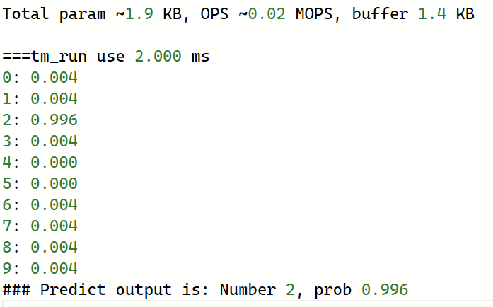
TinyMaix XR806 Port
首先,仓库地址:
https://github.com/YuzukiHD/TinyMaix-XR806测试跑分结果:
config mnist (SRAM) cifar vww96 (Flash XIP) 32K Cache mbnet128 (Flash XIP) 32K Cache mbnet128 (Flash XIP) no Cache O0 CPU 2 134 459 844 42530 O1 CPU 1 104 453 712 35576 make menuconfig的时候可以找到配置项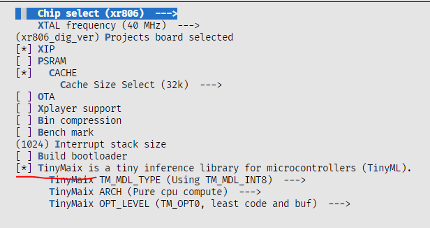
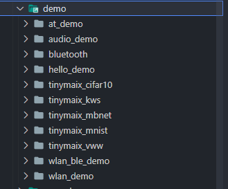
同时也提供了一些demo可供使用
-
回复: SDK目录下面target的作用是什么呢?发布在 MR Series
target 目录
target目录用于存放目标板相关的配置以及sdk和toolchain生成的规格。target/
├── allwinner
├── Config.in
├── imagebuilder
├── Makefile
├── sdk
└── toolchain
快捷跳转命令:cdevice。 -
回复: v851s tf卡启动失败发布在 V Series
@yelong98 在 v851s tf卡启动失败 中说:
[02.382][mmc]: MMC Device 2 not found
[02.386][mmc]: mmc 2 not find, so not exit这个不是报错,正常启动也会显示这个,估计是内核panic了,检查下rv小核的固件没关
